MEMS Microphone Hookup Guide
 jenfoxbot
Introduction
Introduction
The SparkFun MEMS microphone breakout board is a simple and easy-to-use microphone for a variety of sound-sensing projects. The on-board microphone is a low-power, omnidirectional microphone with an analog output. It works for both near and long-range uses and is particularly good for portable applications due to its low power consumption. Possible applications include: smartphones, digital video cameras, and keeping an "ear" on your pets while you're away. Below are boards that breakout the ADMP401 and ICS-40180 microphones.
Read this hook-up guide to get an overview each breakout board and how to use it, including its technical specifications, how to hook it up to a microcontroller, and an example code to get started!
Questions? Feedback? Want to share an awesome project you built using this sensor? Write a comment at the end of this tutorial!
Suggested Reading
To successfully use the SparkFun MEMS microphone breakout board, you'll need to be familiar with Arduino microcontrollers, analog (aka ADC) input, and sound waves. For folks new to these topics, check out the following resources to get a feel for the concepts and verbiage used throughout this tutorial.
What is an Arduino?
Installing Arduino IDE
Analog vs. Digital
RedBoard Qwiic Hookup Guide
We also suggest reading the following for more information about sound and specifications for the IC that is populated on your version of the MEMs microphone breakout.
- The Wikipedia page on the science of sound!
- And finally, and most importantly, the datasheet for your IC!
Hardware Overview
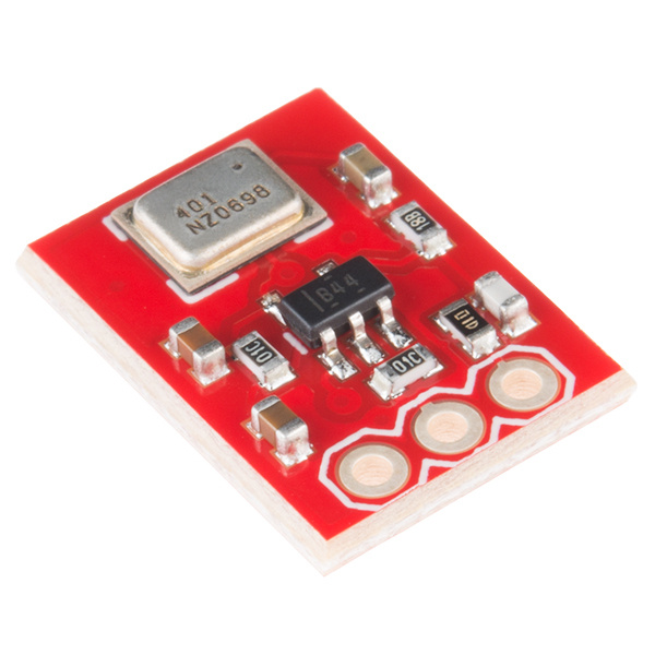
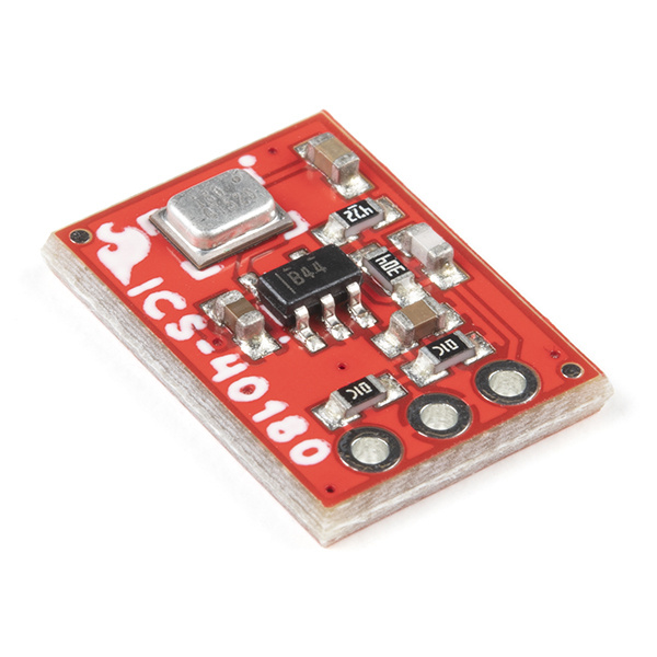
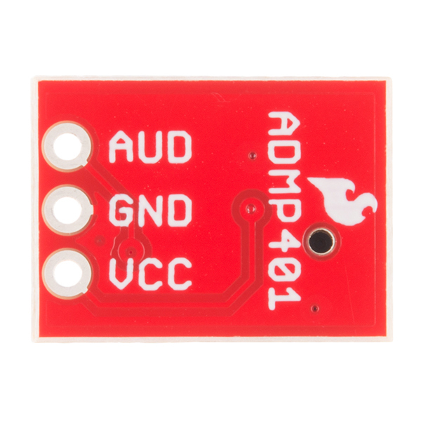
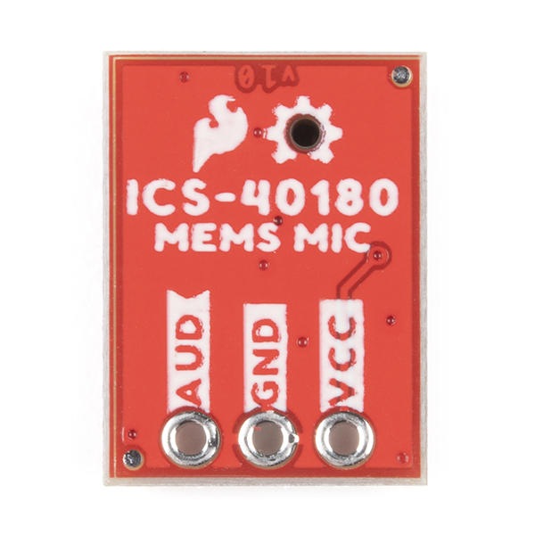
The SparkFun MEMS Microphone breakout board breaks out the microphone for sound detection. Each version breaks out the ADMP401 and ICS-40180 on the top side of the board. The signal is amplified with the OPA344 OpAmp.
 |
 |
| Top View of ADMP401 Breakout | Top View of ICS-40180 Breakout |
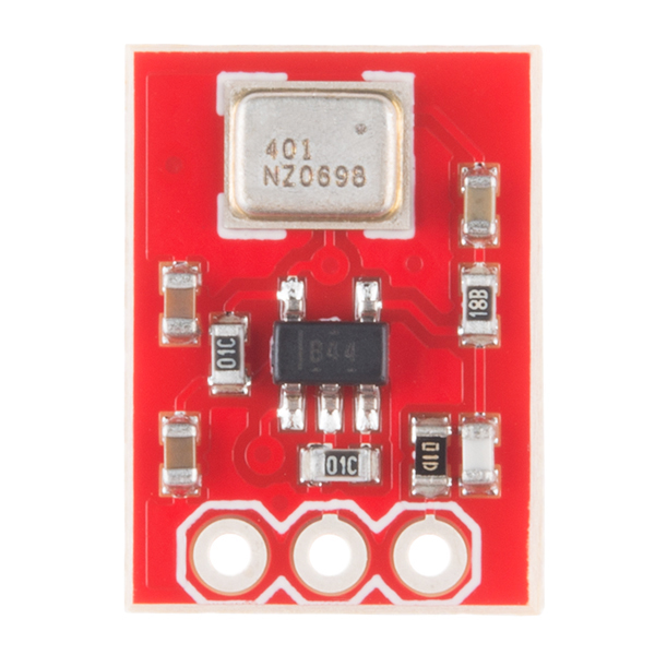
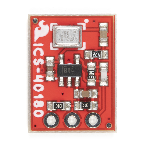
The board receives audio input from the bottom of the board. There are three ports, which are labeled next to each pin.
 |
 |
| Bottom View of ADMP401 Breakout | Bottom View of ICS-40180 Breakout |
- AUD - Audio signal output.
- VCC - Voltage input (1.5V to 3.3V). To power this lil' mic, use a DC voltage with a supply current of about 250μA for ADMP401 or 260μA for ICS-40180. We'll be using 3.3V from an Arduino's.
- GND - Ground.
For technically-minded folks, here are some of the features of the ADMP401 and ICS-40180. Make sure to check out datasheet for the ADMP401 or ICS-40180 for a complete overview of the microphone.
| Electrical Characteristics | ADMP401 | ICS-10480 |
|---|---|---|
| High Signal-to-Noise Ratio ("SNR") | 62 dbA | 65 dbA |
| Sensitivity | about -42 dBV | about -38 dBV |
| Flat Frequency Response | 100 Hz to 15 kHz | 60 Hz to 20 kHz |
| Low Current Consumption | <250 μA @ 3.3V | <260 μA @ 3.3V |
| Maximum Acoustic Input | 120 dB | 124 dB |
The SparkFun breakout board includes an amplifier with a gain of 67 for the ADMP401 and a gain of 65 for the ICS-10480, which is more than sufficient for the microphones. The amplifier's AUD output will float at one-half Vcc when there is no sound. When held at arms length and talked into, the amplifier will produce a peak-to-peak output of about 200 mV.
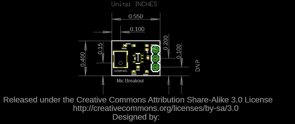
Board Dimensions
The board dimensions for the breakout are 0.55"x 0.40". The location of the audio input and header pins for each microphone is the same even though the size of the IC and locations of the components are different.
 |
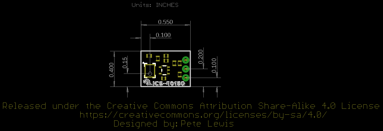 |
| Board Dimensions for ADMP401 | Board Dimensions for ICS-40180 |
Hardware Hookup (Quickstart)
If all of this is super familiar, here's all you need to get started:
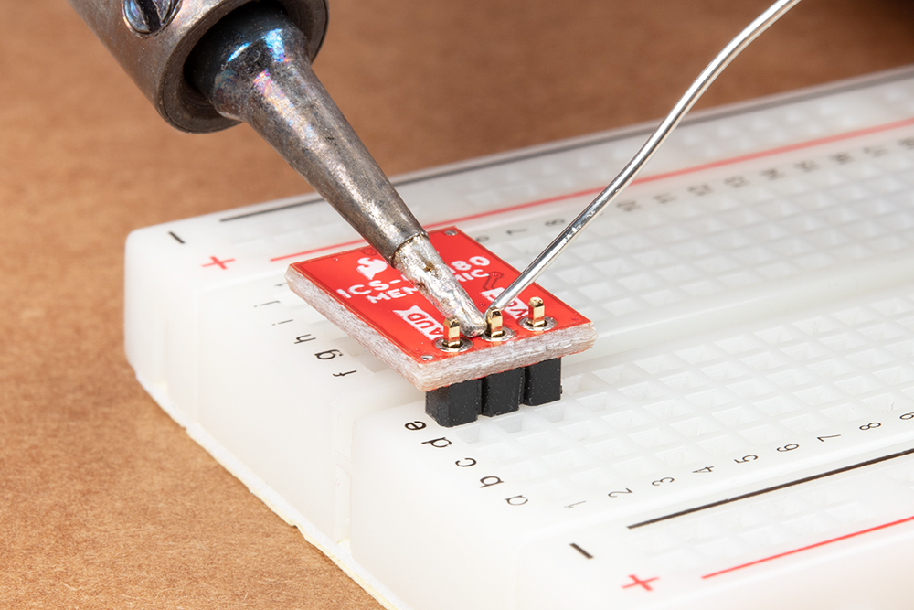
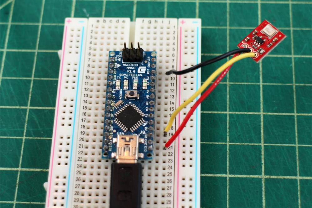
For a temporary connection, you can use IC hooks. For a permanent connection, we recommend soldering three wires (or headers) to each MEMS microphone breakout board ports.
Connect the Vcc port to 3.3V (or anything between 1.5 and 3.3V) and the GND port to ground.
Connect the AUD port to an analog (ADC) input on a microcontroller.
Read in the ADMP401 analog signal and measure/record all the sounds! (Also remember it's a sound signal, so you'll likely want to use the amplitude of the sound wave rather than the raw voltage output.)
 |
 |
| Wires Soldered to ADMP401 | IC Hook Connected to ICS-40180 |
 |
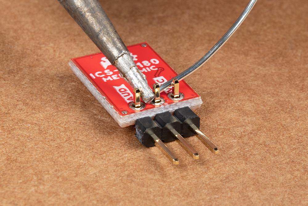 |
| Straight header pins being soldered to MEMS microphone. | Right angle header pins being soldered to MEMS microphone. |
Hardware Hookup
For a more in-depth example, follow along with the following steps:
For a temporary connection, you can use IC Hooks. For a permanent connection, solder three wires (or header pins) to the breakout board ports. We recommend using the following colors to easily distinguish the board ports. If you do not have the color wire available, you can always select a different color as well.
- red for Vcc
- black for GND
- yellow (or some other color) for AUD
Connect the Vcc port to the 3.3 V output of a microcontroller (or any power supply between 1.5 and 3.3 V).
Connect the GND port to GND on the microcontroller.
Connect the AUD port to an analog, or ADC, input on the microcontroller. In this case, we are using A0.
 |
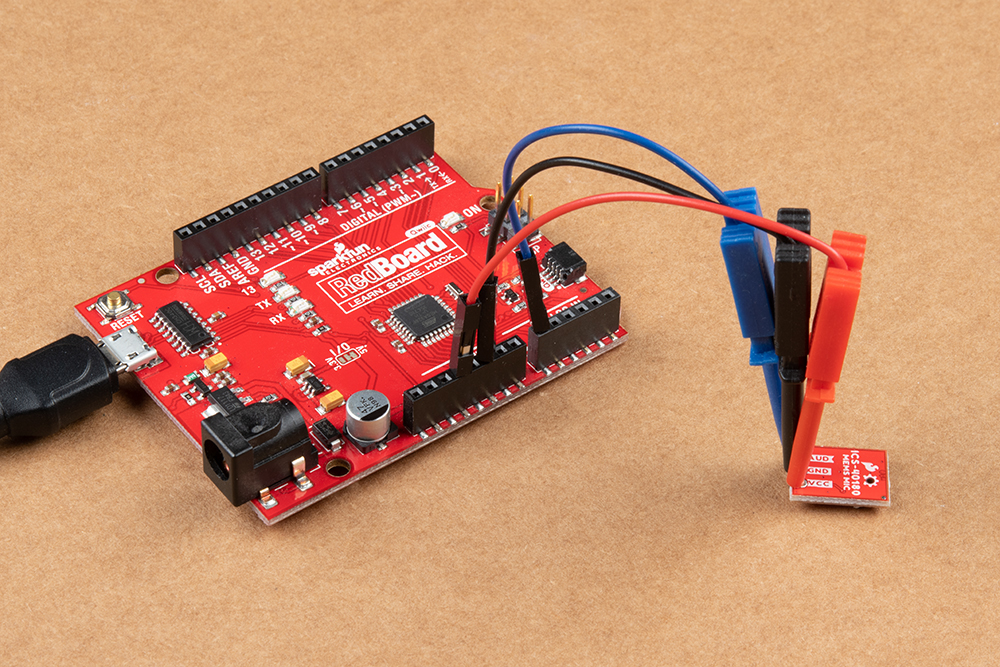 |
| Wire Connected to Arduino | IC Hooks Connected to Arduino |
You can also use the following hookup table as a quick reference.
| Arduino | MEMS Microphone |
|---|---|
| A0 | AUD |
| GND | GND |
| 3.3V | VCC |
The next section will cover how to read the audio signal from the microphone to a microcontroller.
Arduino Software Example
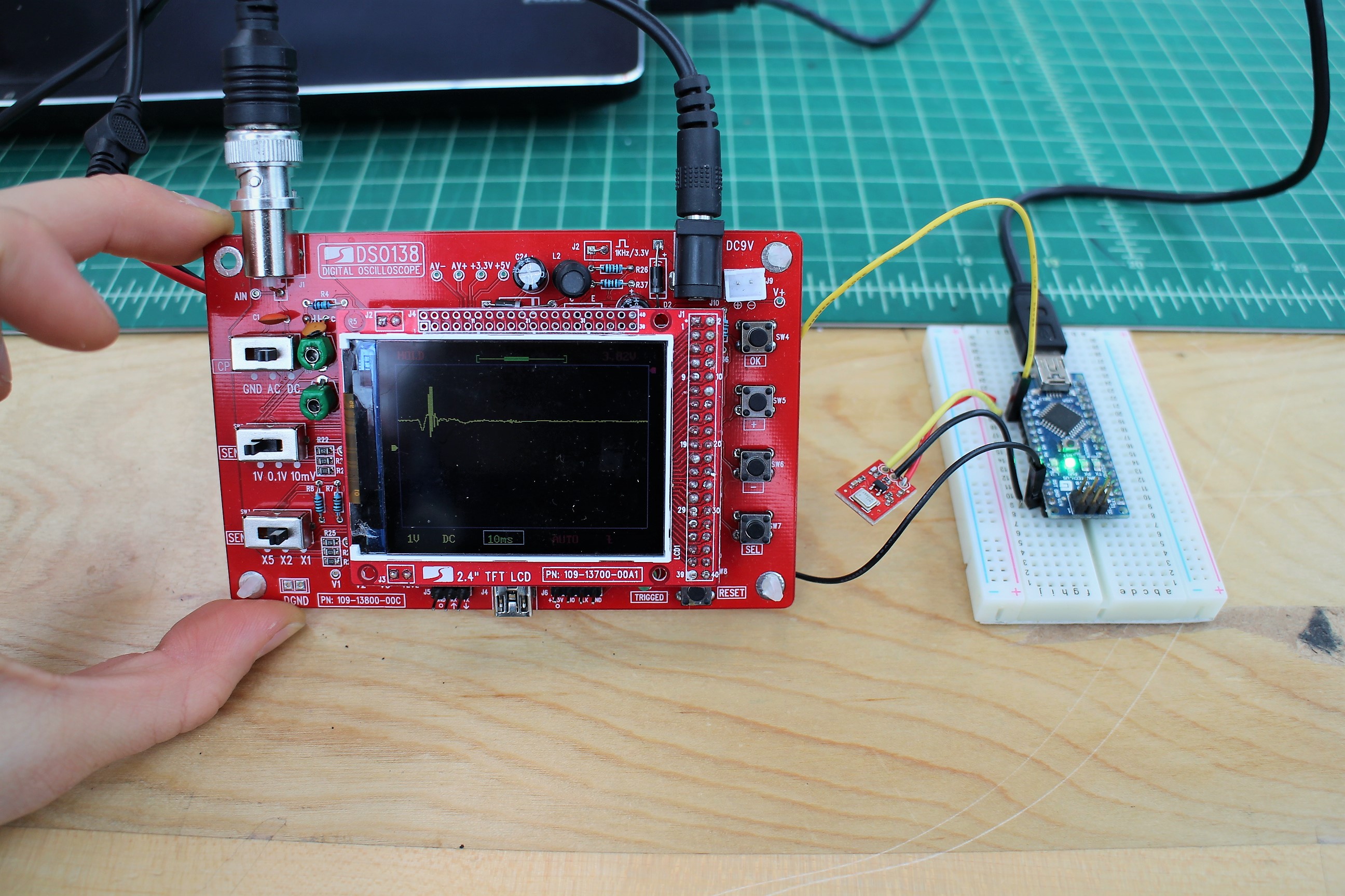
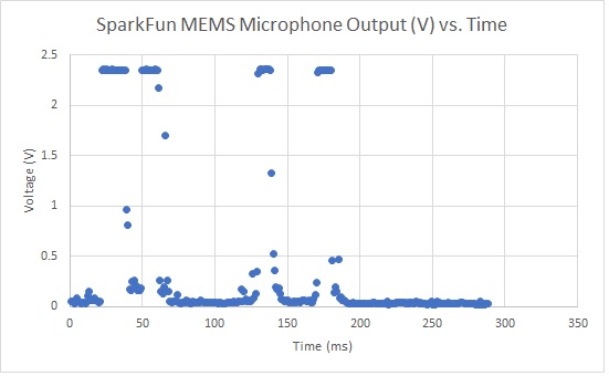
The ADMP401 signal output is a varying voltage. When all is quiet (shhhh), the AUD output will float at one-half the power supply voltage. For example, with a 3.3V power supply, the AUD output will be about 1.65V. In the photo below, the yellow marker on the left side of the oscilloscope screen marks the zero axis for the voltage (aka V = 0). The pulse is the AUD output of a finger snap close to the mic.
Converting ADC to Voltage
The microcontroller analog (ADC) input converts our audio signal into an integer. The range of possible ADC values depends on which microcontroller you are using. For an Arduino microcontroller with an ATmega328P, the analog resolution is 10-bits. This range is between 0 and 1023, so the resolution of our ADC measurement is 1024. To convert our analog measurement into a voltage, we use the following equation:

In our case, the ADC Resolution is 1024, and the System Voltage 3.3 V. We'll need to add this equation in our code to convert our ADC Reading into a voltage.
But Wait, What Are We Actually Measuring??
For many applications that deal with sound (which is a wave), we're mostly interested in the amplitude of the signal. In general, and for the sake of simplicity, a larger amplitude means a louder sound, and a smaller amplitude means a quieter sound (and the sound wave frequency roughly corresponds to pitch). Knowing the amplitude of our audio signal allows us to build a sound visualizer, a volume unit ("VU") meter, set a volume threshold trigger, and other cool and useful projects!
To find the audio signal amplitude, take a bunch of measurements in a small time frame (e.g. 50 ms, the lowest frequency a human can hear). Find the minimum and maximum readings in this time frame and subtract the two to get the peak-to-peak amplitude. We can leave it at that, or divide the peak-to-peak amplitude by a factor of two to get the wave amplitude. We can use the ADC integer value, or convert this into voltage as described above.
Example Code
/***************************
  Simple Example Sketch for the SparkFun MEMS Microphone Breakout Board

**************************/

// Connect the MEMS AUD output to the Arduino A0 pin
int mic = A0;

// Variable to hold analog values from mic
int micOut;

void setup() {
  Serial.begin(9600);

}

void loop() {
  // read the input on analog pin 0:
  micOut = analogRead(mic);

  // print out the value you read:
  Serial.println(micOut);

}Below is a simple example sketch to get you started with the MEMS microphone breakout board. You can find the code in the GitHub repo as well. The code, written for an Arduino microcontroller, includes a conversion equation from the ADC Reading to voltage, a function to find the audio signal peak-to-peak amplitude, and a simple VU Meter that outputs to the Arduino Serial Monitor. For a more visual output, you can also use the Serial Plotter.
Be sure to read the comments in the code to understand how it works and to adapt it to fit your needs. Select your Arduino board, COM port, and hit the upload button.
language:c
/***************************
 * Example Sketch for the SparkFun MEMS Microphone Breakout Board
 * Written by jenfoxbot <jenfoxbot@gmail.com>
 * Code is open-source, beer/coffee-ware license.
 */

// Connect the MEMS AUD output to the Arduino A0 pin
int mic = A0;

// Variables to find the peak-to-peak amplitude of AUD output
const int sampleTime = 50;
int micOut;

//previous VU value
int preValue = 0;

void setup() {
  Serial.begin(9600);
}

void loop() {
   int micOutput = findPTPAmp();
   VUMeter(micOutput);
}


// Find the Peak-to-Peak Amplitude Function
int findPTPAmp(){
// Time variables to find the peak-to-peak amplitude
   unsigned long startTime= millis();  // Start of sample window
   unsigned int PTPAmp = 0;

// Signal variables to find the peak-to-peak amplitude
   unsigned int maxAmp = 0;
   unsigned int minAmp = 1023;

// Find the max and min of the mic output within the 50 ms timeframe
   while(millis() - startTime < sampleTime)
   {
      micOut = analogRead(mic);
      if( micOut < 1023) //prevent erroneous readings
      {
        if (micOut > maxAmp)
        {
          maxAmp = micOut; //save only the max reading
        }
        else if (micOut < minAmp)
        {
          minAmp = micOut; //save only the min reading
        }
      }
   }

  PTPAmp = maxAmp - minAmp; // (max amp) - (min amp) = peak-to-peak amplitude
  double micOut_Volts = (PTPAmp * 3.3) / 1024; // Convert ADC into voltage

  //Uncomment this line for help debugging (be sure to also comment out the VUMeter function)
  //Serial.println(PTPAmp);

  //Return the PTP amplitude to use in the soundLevel function.
  // You can also return the micOut_Volts if you prefer to use the voltage level.
  return PTPAmp;
}

// Volume Unit Meter function: map the PTP amplitude to a volume unit between 0 and 10.
int VUMeter(int micAmp){

  // Map the mic peak-to-peak amplitude to a volume unit between 0 and 10.
   // Amplitude is used instead of voltage to give a larger (and more accurate) range for the map function.
   // This is just one way to do this -- test out different approaches!
  int fill = map(micAmp, 23, 750, 0, 10);

  // Only print the volume unit value if it changes from previous value
  while(fill != preValue)
  {
    Serial.println(fill);
    preValue = fill;
  }
}
Resources and Going Further
Now that you've connected your MEMS microphone breakout, it's time to incorporate it into your own project! For more information, check out the resources below:
- ADMP401
- ICS-40180
If you run into trouble getting, or understanding, an audio signal output from the MEMS mic breakout board, try using a multimeter and/or an oscilloscope to measure the voltage output of the signal in quiet and loud settings. If you're still stuck, check out our forums and we'll help you troubleshoot.
After you've read in the MEMS microphone and have a good handle on the signal output, you're ready to start using it for practical microphone applications! Here are a few ideas to get you started:
- Build a music visualizer! Here's a sample sketch for the music visualizer shown in the SparkFun Simple Sketches example.
- Record sounds and play them back! You'll also need a speaker, an amplifier transistor, and some pushbuttons (and some code. Here's an open-source mbed example).
- Make a sound-reactive EL Wire costume and replace the Sound Detector with the MEMS Microphone!
- Make a Bark Back Pet Monitor with a Raspberry Pi to record the sound levels in your home, upload the data MQTT, and trigger an audio player to when the volume reaches a threshold.
Or check out these other audio related tutorials below.
Binary Blaster Assembly Guide
Electret Mic Breakout Board Hookup Guide
Spectacle Sound Kit Hookup Guide
The 970-HA-JOKES Payphone Project
Happy building!