MEMS Microphone Hookup Guide
Contributors:
 jenfoxbot
Hardware Hookup (Quickstart)
If all of this is super familiar, here's all you need to get started:
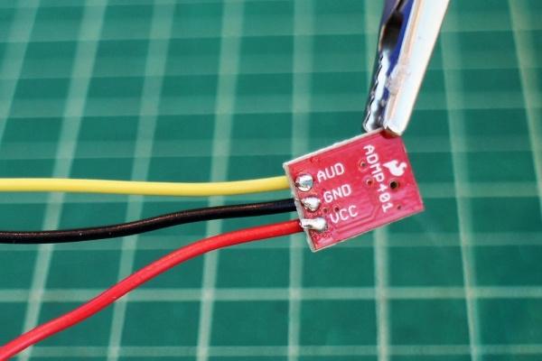
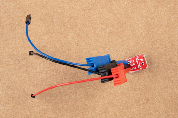
For a temporary connection, you can use IC hooks. For a permanent connection, we recommend soldering three wires (or headers) to each MEMS microphone breakout board ports.
Connect the Vcc port to 3.3V (or anything between 1.5 and 3.3V) and the GND port to ground.
Connect the AUD port to an analog (ADC) input on a microcontroller.
Read in the ADMP401 analog signal and measure/record all the sounds! (Also remember it's a sound signal, so you'll likely want to use the amplitude of the sound wave rather than the raw voltage output.)
 |
 |
| Wires Soldered to ADMP401 | IC Hook Connected to ICS-40180 |
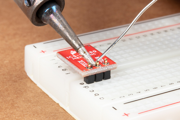
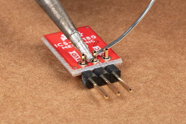
Note: You can use any connection as explained above to connect. If you decide to solder straight header pins, we recommend inserting the straight header pin's tail from the top of the board so that the audio input for the microphone is facing away from a surface. However, depending on your application, you can also insert the pins on the side as well. For a low profile application, you will want to use right angle header pins.
 |
 |
| Straight header pins being soldered to MEMS microphone. | Right angle header pins being soldered to MEMS microphone. |