MEMS Microphone Hookup Guide
 jenfoxbot
Hardware Hookup
For a more in-depth example, follow along with the following steps:
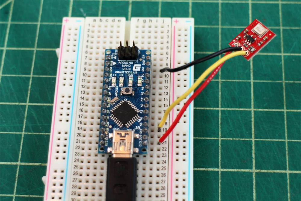
For a temporary connection, you can use IC Hooks. For a permanent connection, solder three wires (or header pins) to the breakout board ports. We recommend using the following colors to easily distinguish the board ports. If you do not have the color wire available, you can always select a different color as well.
- red for Vcc
- black for GND
- yellow (or some other color) for AUD
Connect the Vcc port to the 3.3 V output of a microcontroller (or any power supply between 1.5 and 3.3 V).
Connect the GND port to GND on the microcontroller.
Connect the AUD port to an analog, or ADC, input on the microcontroller. In this case, we are using A0.
 |
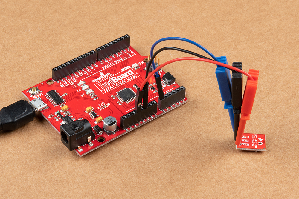 |
| Wire Connected to Arduino | IC Hooks Connected to Arduino |
You can also use the following hookup table as a quick reference.
| Arduino | MEMS Microphone |
|---|---|
| A0 | AUD |
| GND | GND |
| 3.3V | VCC |
The next section will cover how to read the audio signal from the microphone to a microcontroller.