LTE GNSS Breakout - SARA-R5 Hookup Guide
 El Duderino,
  PaulZC
 Hardware Overview
Let's take a closer look at the SARA-R510M8S module and other features of the SparkFun LTE GNSS Breakout - SARA-R5.
u-blox SARA-R510M8S
The SARA-R510M8S module from u-blox combines u-blox's UBX-R5 cellular chipset with their M8 GNSS receiver chipset to provide a 5G-Ready wireless IoT device complete with positioning data all on a single chip. For a thorough overview of the SARA-R5 modules, please review the SARA-R5 datasheet.

The u-blox UBX-R5 chipset boasts some impressive features including:
- Multi-region LTE M1 and NB2 Half-Duplex.
- Built-in end-to-end security with hardware-based root of trust inside a discrete secure element.
- A full security suite with foundation, design, end-to-end security as well as access control.
- Over-the-air cirital firmware updates and services enabled via the uFOTA client/server solution.
- Optimized for ultra-low power consumption.
The built-in u‑blox M8 GNSS receiver provides accurate and reliable positioning with a separate GNSS antenna interface for an external antenna. The GNSS position data is enhanced with u-blox's CellLocate® data. The receiver outputs data in NMEA format which can be parsed through our u-blox SARA-R5 Arduino Library.
The SARA-R5 supports many different forms of data communication from full TCP/IP sockets and packet switched data, through HTTP Get/Put/Post, FTP (the SARA has a built-in file system), Ping, to good old SMS text messaging!
The board also includes the necessary SMA connectors for external GNSS and LTE antennas as well as a nano SIM card slot.
SARA-R5 UARTs and USB-C Connectors
The LTE GNSS Breakout has three USB-C connectors on board to provide power or interact with the module's two hardware UARTs as well as the SARA Diagnostic port to access the SARA's trace log1. The UART data for both the UART1 and UART2 USB-C connectors is translated to USB data through a CH340C USB-to-Serial adapter IC.
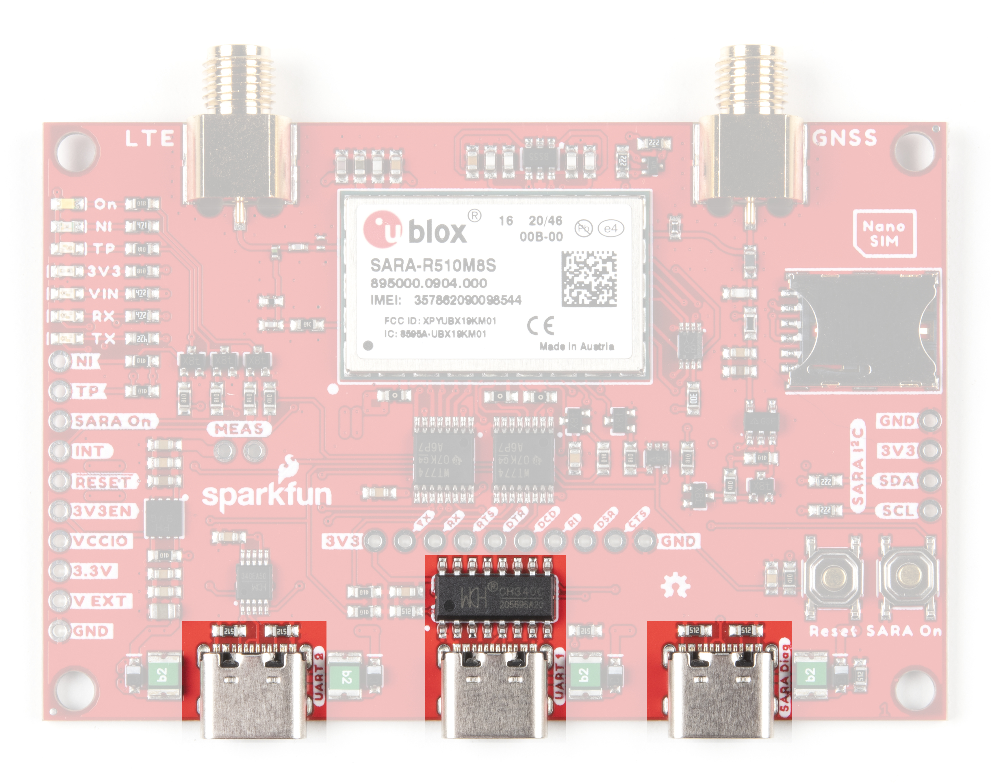
The breakout comes pre-configured to support a single UART interface (either Variant 0 or Variant 1). Enable any of the dual UART interfaces (Variants 2-4) by adjusting several jumpers on the board (refer to section 2.5.1 of the SARA-R5 datasheet and section 1.9.1. of the SARA-R5 System Integration Manual for more information on the UART variants). Read on to the Hardware Assembly section for detailed instructions on how to configure the breakout to use the dual UART variants.
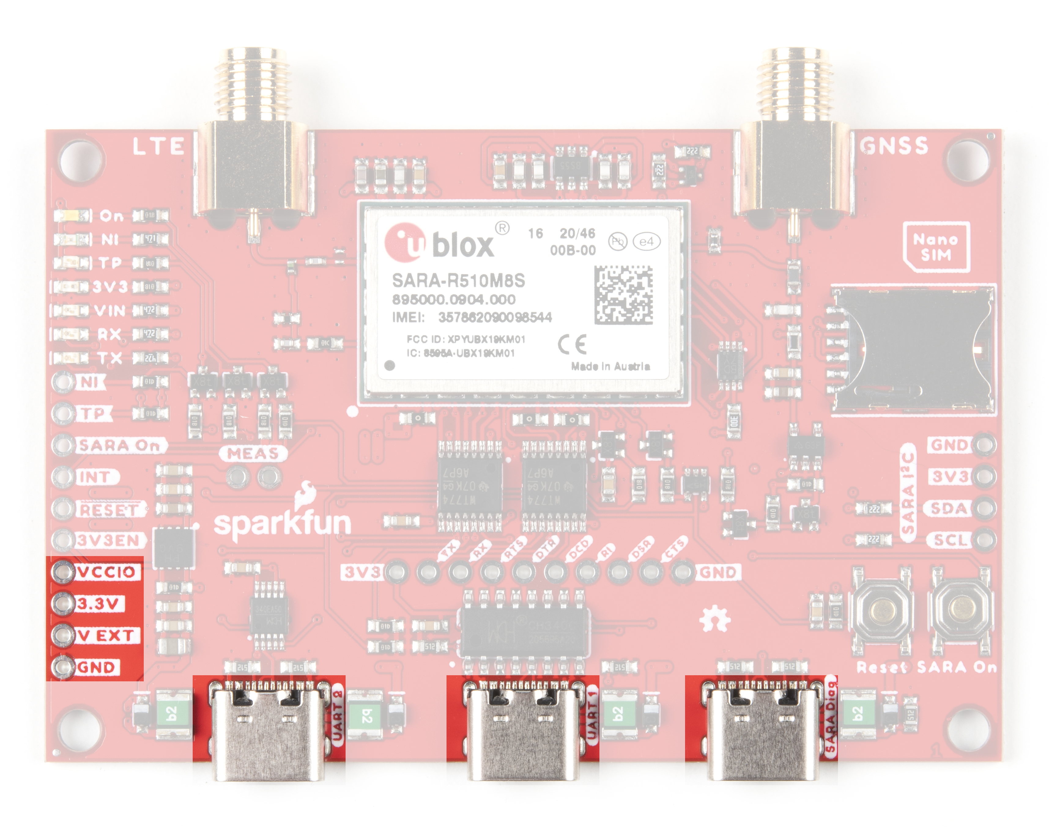
Power Supply
The LTE GNSS Breakout is designed to accept power either over USB-C or the dedicated power pin, V EXT. The V EXT pin feeds into the 3.3V regulator which accepts a supply voltage between 3.7V to 6.0V. u-blox designed the SARA-R510M8S to be power-efficient with a variety of low-power and sleep modes and pulls a max of 395mA during transmission (Tx).
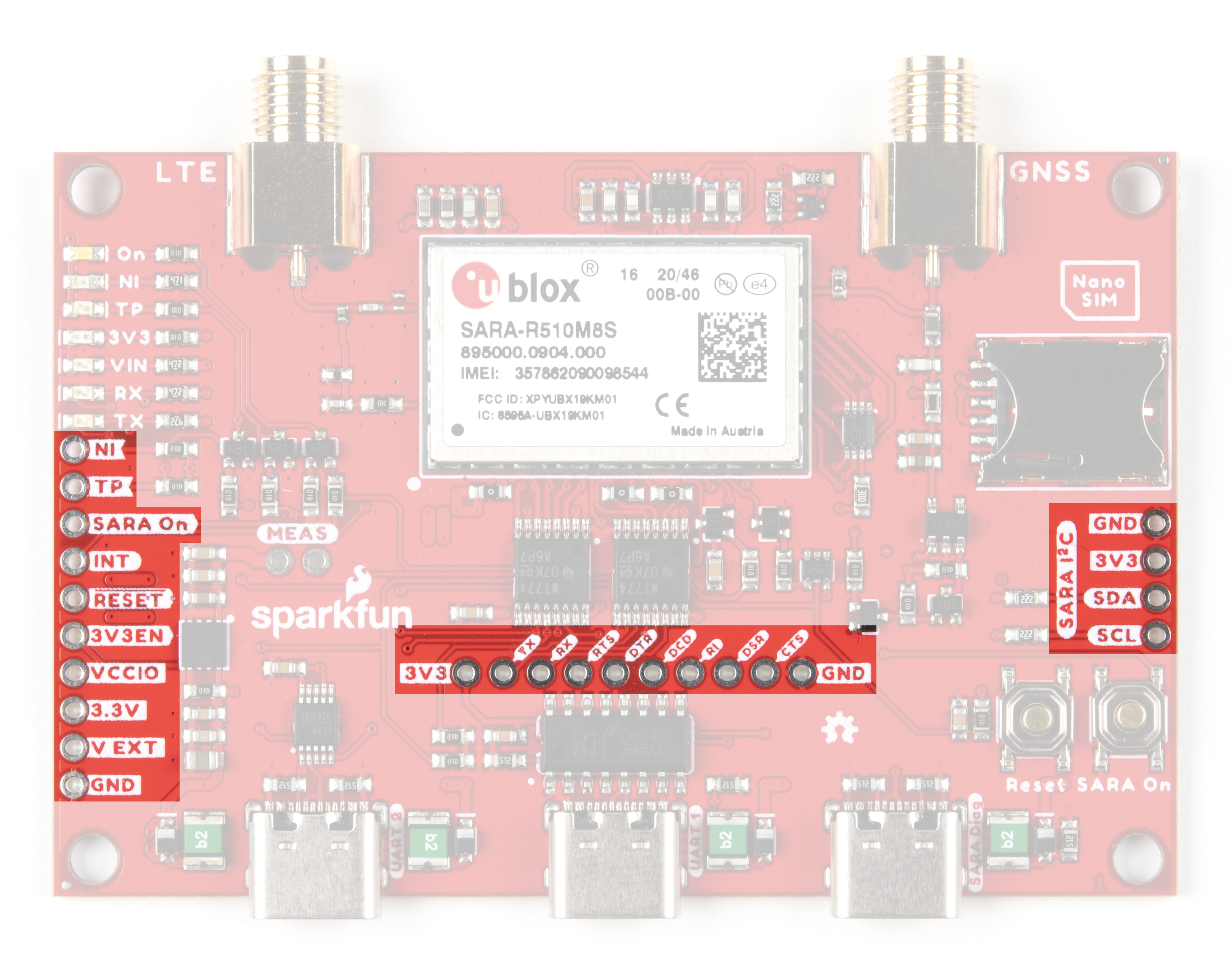
Plated Through Hole (PTH) Interfaces
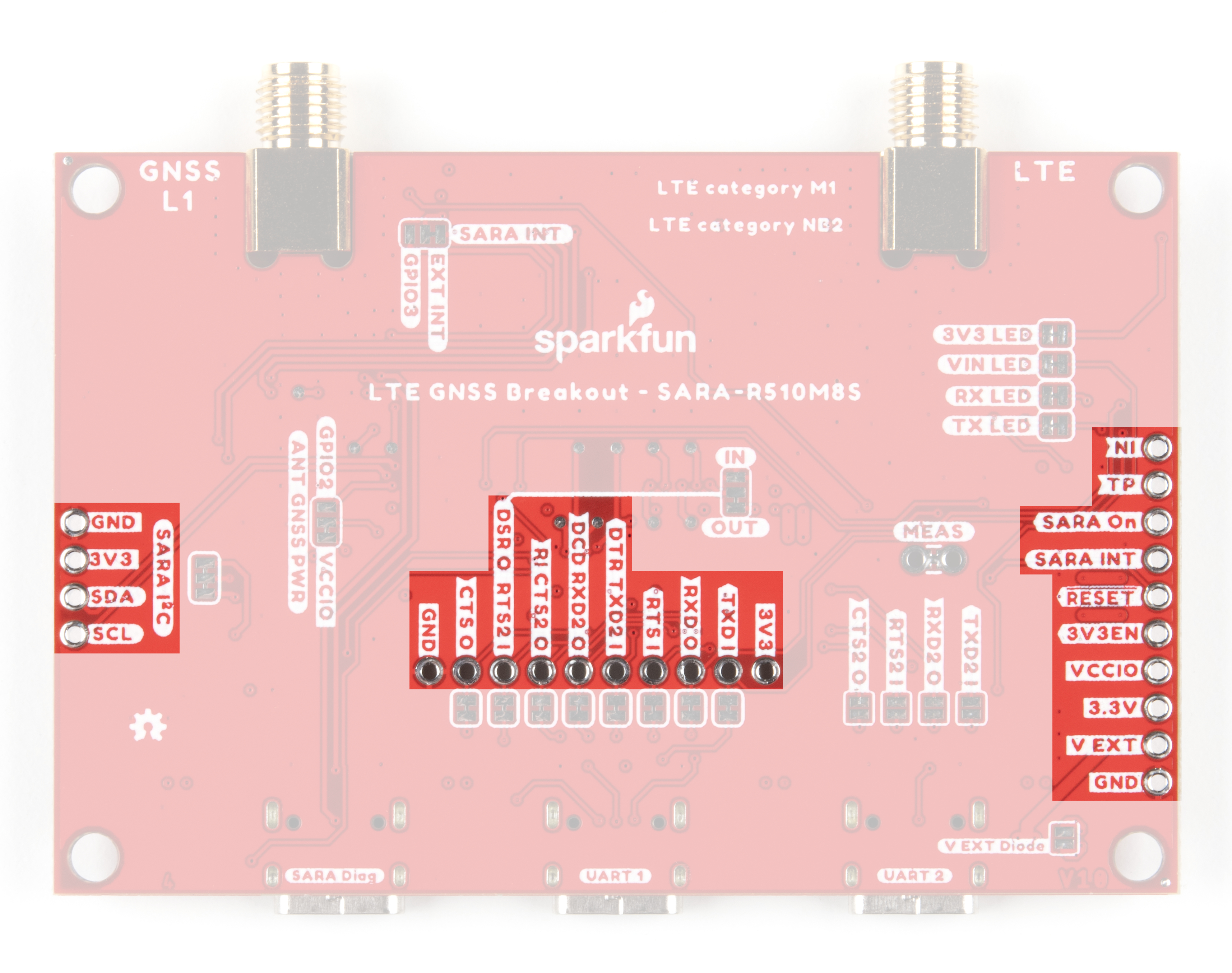
As expected with a breakout, we've routed nearly all functional pins from the SARA-R510M8S to plated through-hole (PTH) headers for users to directly interact with them. We've already covered the power PTHs so let's take a look at the other pins on the LTE GNSS Breakout.
UART PTHs
In the center of the board you'll find the Serial UART PTH header. This header is normally netted to the UART1 USB-C connector through a CH340 serial converter IC for single-UART operation. You can isolate any of the pins to directly interact with them by opening the jumpers on the bottom of the board (more on that in the following "Solder Jumpers" section).
The behavior of some of the pins on this header change depending on whether the SARA-R5 is in single or dual-UART mode. The table below outlines their functionality when in either UART mode. Read on to the Hardware Assembly section for instructions on how to enable the UART2 USB-C connection.
| UART Header Pin Label | Single UART Behavior | Dual UART Behavior |
|---|---|---|
| 3V3 | 3.3V Out | |
| TXD I | UART1 Serial Data Input | |
| RXD O | UART1 Serial Data Output | |
| RTS I | UART1 Request to Send Input | |
| DTR / TXD2 I | Data Terminal Ready | UART2 Serial data input |
| DCD / RXD2 O | Data Carrier Detect | UART2 Serial data |
| RI / CTS2 O | Ring Indicator | UART2 Clear to Send Output |
| DSR O / RTS2 I | Data Set Ready Output | UART2 Request to Send Input |
| CTS O | UART1 Clear to Send Output | |
| GND | Ground | |
Take note these pins are level shifted from the SARA-R5's 1.8V logic to 3.3V logic for the PTHs and 5V logic for USB. Modify the board to isoloate these signals and connect them to an Arduino development board to use this breakout with the SparkFun u-blox SARA-R5 Arduino Library. Read on to the Hardware Assembly and Arduino Library/Example sections for more information on using the board with the u-blox SARA-R5 Arduino library.
Additional GPIO PTHs
The board routes the pins for the SARA-R5 I2C bus to a labeled PTH header on one side of the board. On the other side, the SARA On, SARA External Interrupt, Reset and 3V3 Enable pins are broken out along with indicator outputs for Time Pulse Output (labeled TP) and Network Status Indication (labeled NI).
Control power to the SARA-R5 with the SARA On pin. Pull it low for 5 seconds and release to turn the module off. When powered down, pull the pin low briefly to turn it on.
The TP and NI pins are tied to GPIO1 and GPIO6, respectively as well as indicator LEDs with the same labels. The NI pin state alternates between full LOW (no service/not registered), full HIGH (data transmission) and various pulse lengths to indicate other network statuses when configured using the +CREG AT command. The TP pin behaves as a GNSS / LTE Timing Pulse (PPS) and toggles LOW/HIGH when configured by the +UTIME-1,1 AT command. Refer to section 17 of the AT Command Manual for more information about using GPIO pins for these behaviors.
Indicator LEDs
The breakout includes seven LEDs to indicate the status of the SARA-R5 labeled: On, NI, TP, 3V3, VIN, RX and TX.
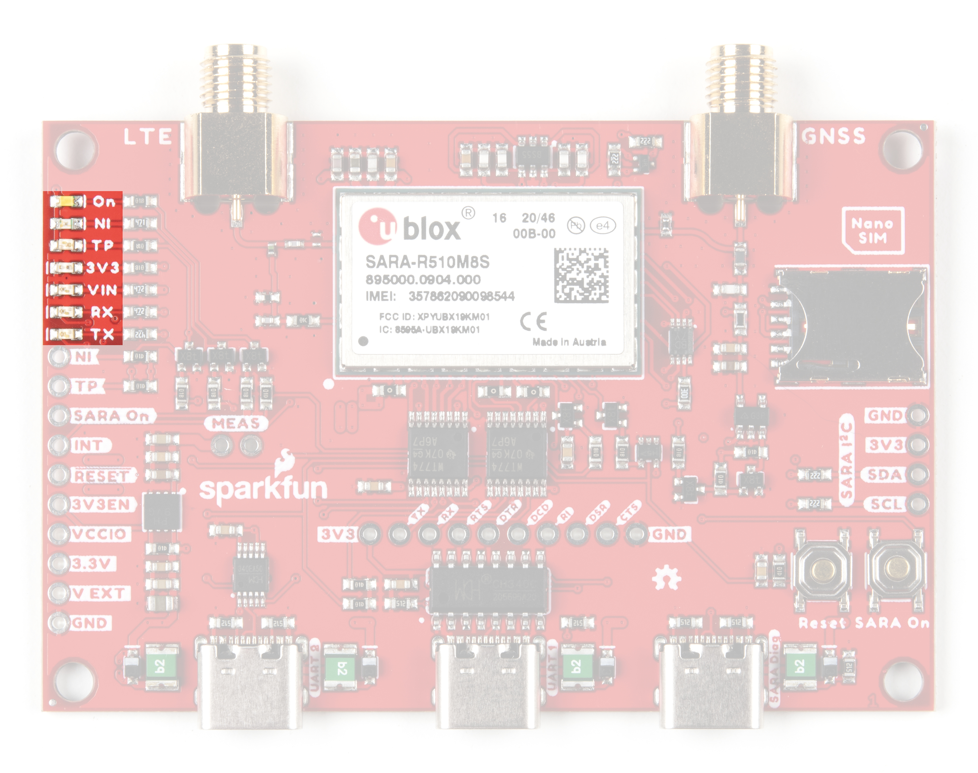
The voltage and power indicator LEDs are fairly self-explanatory. When power is applied to VIN or 3.3V, those respective indicator LEDs turn on (unless the solder jumpers tied to their respective circuits have been opened). The On LED indicates whether or not the SARA-R5 module is powered on. The RX and TX LEDs are tied to the RX/TX lines on UART1 to show when those are transmitting data.
The NI LED shows the cellular network status when GPIO1 is configured to act as a network status indicator output. The NI LED alternates from full Off (No service), full On (Data Transmission) as well as various pulse lengths to show different network statuses. Refer to section 17.1.3 of the AT Command Manual for the AT commands and description of this LED and the GPIO1/NI pin's behavior for different network states.
The TP LED can be configured as a visual indicator of the time pulse output signal to provide time information for the LTE system. When enabled, the LED will pulse once per second. Refer to section 17 of the AT Command Manual for the command set to configure this LED and TP/GPIO6 pin.
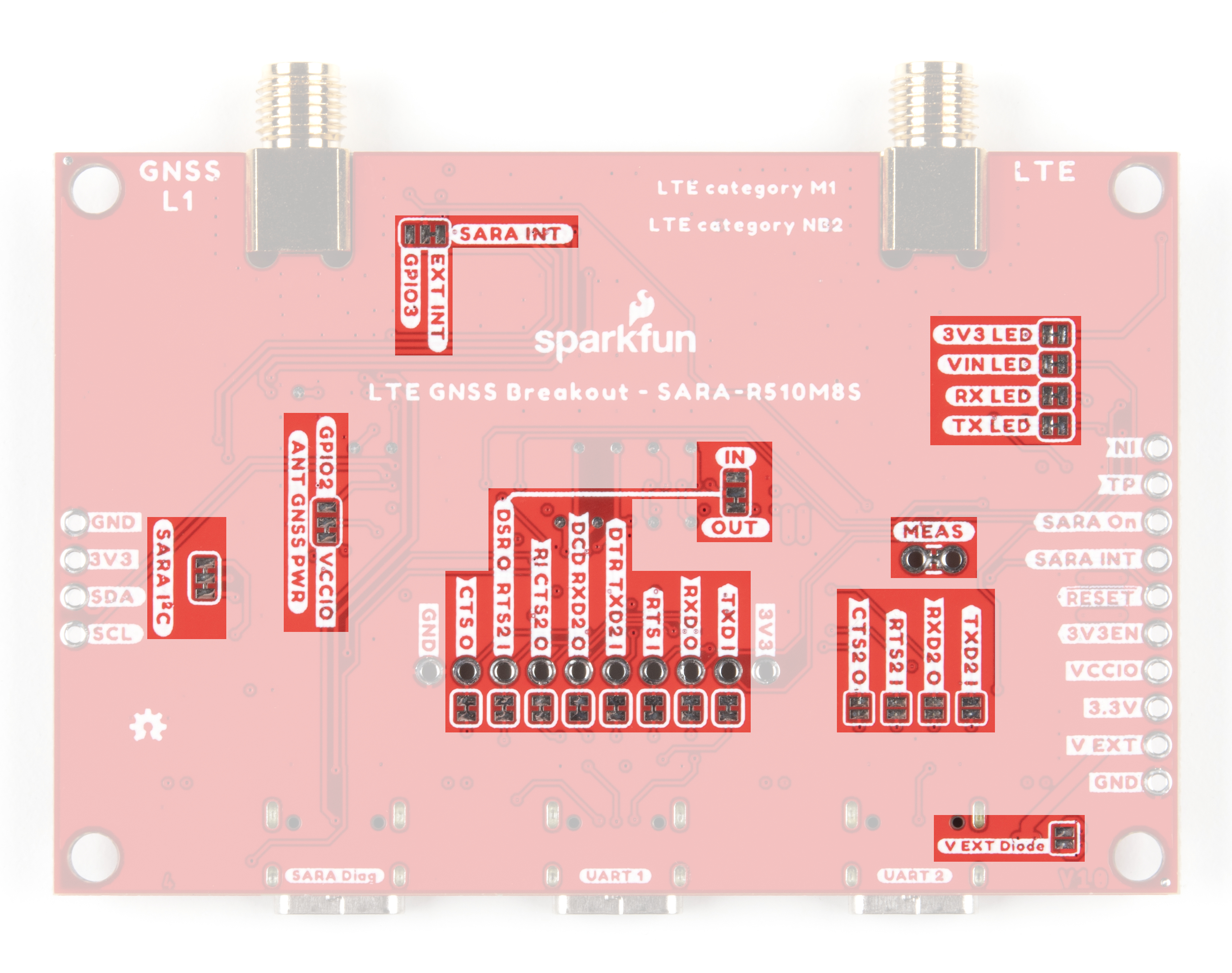
Solder Jumpers
The LTE/GNSS Breakout has a host of solder jumpers to adjust the behavior of the board and components on it. The tables below outline what each jumper does, their default states and some notes about their behavior.
| Jumper Label | Description | Default State | Notes |
|---|---|---|---|
| SARA I2C | Pulls SARA-R5 I2C lines to 3.3V via a pair of 2.2kΩ resistors. | CLOSED | |
| ANT GNSS PWR | A dual jumper to select power control for the GNSS antenna. | SEE NOTE | By default, GNSS antenna is tied to VCCIO to continuously power it. Switch the jumper from VCCIO to SARA GPIO2 to use that pin to control GNSS antenna power. |
| EXT INT / GPIO 3 | A dual jumper to select which SARA pin is tied to the SARA_INT PTH pin. | SEE NOTE | By default, this jumper routes the external interrupt pin to the PTH header. Adjust it to the pad labeled GPIO3 to tie this general purpose I/O pin to the PTH header instead. |
| IN/OUT | A dual jumper to select the direction of DSR (Data Set Ready) for dual UART communication. | SEE NOTE | By default, this jumper sets DSR as an output. Adjust the jumper to the "IN" side to set DSR as a flow control input. |
| MEAS | Current measuring jumper | CLOSED | Open this jumper to measure the current draw of the board with a multimeter. |
| V EXT Diode | V EXT diode bypass | OPEN | Close this jumper to bypass the external voltage input diode. |
| 3V3 LED | LED power control. | CLOSED | Open to disable the labeled LED. Disabling the LEDs helps reduce total current draw of the breakout. |
| VIN LED | CLOSED | ||
| RX LED | CLOSED | ||
| TX LED | CLOSED |
| Jumper Label | Description | Default State | Notes |
|---|---|---|---|
| TXD I | Ties UART1 TX line to the UART1 USB-C connector through the CH340C. | CLOSED | Open this jumper to isolate the TX pin from the USB-C connector for use with an Arduino or other device. |
| RXD O | Ties UART1 RX lne to the UART1 USB-C connector through the CH340C. | CLOSED | Open this jumper to isolate the RX pin from the USB-C connector for use with an Arduino or other device. |
| RTS I | Ties UART1 Request to Send to the UART1 USB-C connector through the CH340C. | CLOSED | Open this jumper to isolate the RTS pin from the CH340C and pull it LOW/0V via a 100kΩ resistor. The RTS pin must be pulled LOW/0V when using RX/TX only for serial communication as used in the Arduino library. |
| DTR TXD2 | CLOSED | Open this jumper to use DTR pin as UART2 data in (TX) for dual UART modes (when the TXD2_I jumper is CLOSED). If the TXD2_I jumper is OPEN, opening this jumper pulls the DTR pin LOW/0V to enable RX/TX only serial communication used in the Arduino library. | |
| DCD | CLOSED | Open the DCD jumper to use the DCD pin as UART2 data out (RX) for dual UART modes. | |
| RI CTS2 O | CLOSED | Open the RI CTS2 O jumper to use the RI pin as UART2 clear to send (CTS) for dual UART modes. | |
| DSR O RTS2 I | CLOSED | Open the DSR O RTS2 I jumper to use the DSR pin as UART2 request to send (RTS) for dual UART modes. | |
| CTS O | Ties UART1 Clear to Send to the UART1 USB-C connector through the CH340C. | CLOSED | Open this jumper to isolate the CTS pin from the USB-C connector for use with an Arduino or other device. |
| TXD2 I | Ties the labeled UART2 pin to the UART2 USB-C connector. | OPEN | Close these jumpers to connect the labeled UART2 pin to the UART2 USB-C connector. Using Dual UART modes requires other jumper manipulation. Read on to the Hardware Assembly section for more detailed instructions. |
| RXD2 O | OPEN | ||
| RTS2 I | OPEN | ||
| CTS2 O | OPEN |
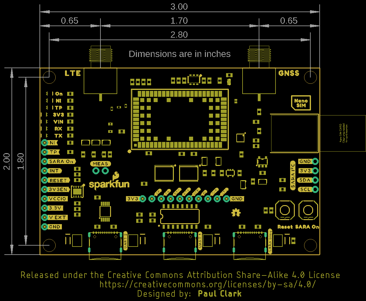
Board Dimensions
The SparkFun LTE GNSS Breakout - SARA-R5 measures 3.0in x 2.0in (76.2mm x 50.7mm) with four mounting holes that fit a 4-40 screw.