LilyPad RGB LED Hookup Guide
 bboyho,
  Gella
Gella 
Basic Color Mixing with Code
Note: This example assumes you are using the latest version of the Arduino IDE on your desktop. If this is your first time using Arduino, please review our tutorial on installing the Arduino IDE.
This example code demonstrates how to display a simple rainbow of colors using the RGB LED. In order to create colors with the RGB LED, you'll have to set each of the LEDs within it individually. The combination of light from the LEDs mixed together creates new colors.
Copy and paste the following code into the Arduino IDE and upload it to your LilyPad Arduino.
language:c
/*
  LilyPad Tri-Color LED: Basic Color Mixing
  Written by: Gella and Ho Yun "Bobby" Chan
  SparkFun Electronics
  https://www.sparkfun.com/products/13735

  Create primary and secondary colors on the tri-color (Red/Green/Blue)
  LED connected to a LilyPad Arduino.

  Tri-Color LED connections:
  R pin to 11
  G pin to 10
  B pin to 9
  - pin to -


  This code is released under the MIT License (http://opensource.org/licenses/MIT)

******************************************************************************/

// This example uses a tri-color, also known as an RGB
// (Red / Green / Blue) LED.
// This example uses digitalWrite() to turn the three LEDs on and off
// in various combinations to create eight primary and secondary colors.

//debug mode, comment one of these lines out using a syntax for a single line comment: //
#define DEBUG 0     //0 = LEDs only
//#define DEBUG 1     //1 = LEDs w/ serial output

// Create integer variables for our LED pins:
#define RGB_red 11
#define RGB_green 10
#define RGB_blue 9

void setup() {

  // Make all of our LED pins outputs:
  pinMode(RGB_red, OUTPUT);
  pinMode(RGB_green, OUTPUT);
  pinMode(RGB_blue, OUTPUT);

#if DEBUG
  Serial.begin(9600); //initialize Serial Monitor
  //while (!Serial);  // Comment out to wait for serial port to connect to Serial Monitor. Needed for native USB.
  Serial.println("Basic Color Mixing w/ a Common Cathode RGB LED");
#endif

}//end setup()

void loop() {

  // This code will step through the six primary and secondary colors, plus white and black.
  // Note: for this particular LED, the wiring shares a common anode (+), which means to
  // turn on the LEDs you will set them LOW instead of HIGH.
  // Keep this in mind as you prototype with the LED and mix your colors.

  // For each of these colors, we'll turn the necessary RGB LEDs on or off.


  // Black (all LEDs off)
  // RGB LEDs:
#if DEBUG
  Serial.println("OFF");
#endif
  digitalWrite(RGB_red, LOW);
  digitalWrite(RGB_green, LOW);
  digitalWrite(RGB_blue, LOW);
  delay(1000);

  // Red (red LED on)
#if DEBUG
  Serial.println("RED");
#endif
  digitalWrite(RGB_red, HIGH);
  digitalWrite(RGB_green, LOW);
  digitalWrite(RGB_blue, LOW);
  delay(1000);

  //Yellow (red and green LEDs on)
#if DEBUG
  Serial.println("YELLOW");
#endif
  digitalWrite(RGB_red, HIGH);
  digitalWrite(RGB_green, HIGH);
  digitalWrite(RGB_blue, LOW);
  delay(1000);

  // Green (green LED on)
#if DEBUG
  Serial.println("GREEN");
#endif
  digitalWrite(RGB_red, LOW);
  digitalWrite(RGB_green, HIGH);
  digitalWrite(RGB_blue, LOW);
  delay(1000);

  // Cyan (blue and green LEDs on)
#if DEBUG
  Serial.println("CYAN");
#endif
  digitalWrite(RGB_red, LOW);
  digitalWrite(RGB_green, HIGH);
  digitalWrite(RGB_blue, HIGH);
  delay(1000);

  // Blue (blue LED on)
#if DEBUG
  Serial.println("BLUE");
#endif
  digitalWrite(RGB_red, LOW);
  digitalWrite(RGB_green, LOW);
  digitalWrite(RGB_blue, HIGH);
  delay(1000);

  // Magenta (red and blue LEDs on)
#if DEBUG
  Serial.println("MAGENTA");
#endif
  digitalWrite(RGB_red, HIGH);
  digitalWrite(RGB_green, LOW);
  digitalWrite(RGB_blue, HIGH);
  delay(1000);

  // White (all LEDs on)
#if DEBUG
  Serial.println("WHITE");
#endif
  digitalWrite(RGB_red, HIGH);
  digitalWrite(RGB_green, HIGH);
  digitalWrite(RGB_blue, HIGH);
  delay(1000);

}//end loop
After uploading your code, the RGB LED will step through a color sequence beginning with all LEDs off ('black'), red, yellow, green, cyan, blue, magenta, and white. Once the color sequence is complete, the program will loop back to the beginning and repeat the sequence.
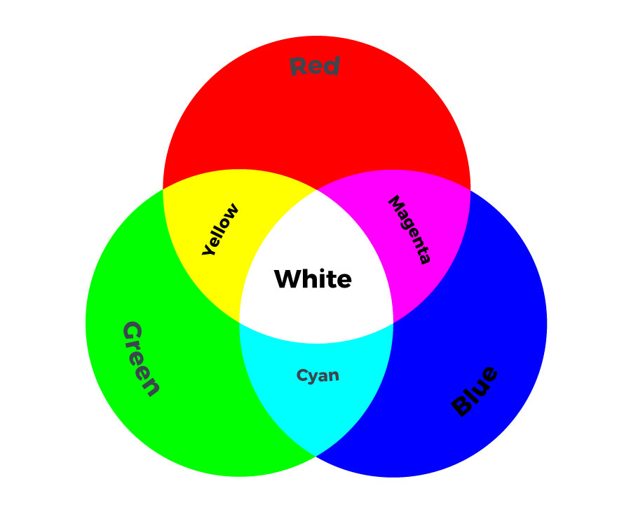
Turning on different combinations of three LEDs inside the RGB LED will create new colors. Combining the primary colors of light (red, green, and blue) gives different results than combining pigments in paints or inks. Turning on all three colors will create white - this is called additive color. Take a look a the graphic below to see what colors combine to create primary and secondary colors with light.