LilyPad RGB LED Hookup Guide
Contributors:
 bboyho,
  Gella
Gella
Introduction
Heads up! This tutorial was written for the LilyPad RGB LED with common cathode. If you are using the LilyPad Tri-Color LED with common anode, please refer to the LilyPad Tri-Color LED Hookup Guide.
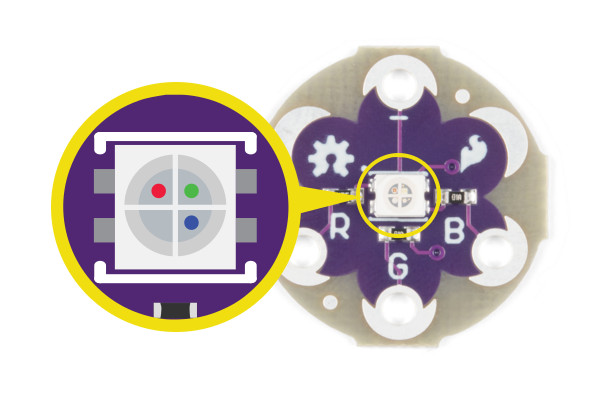
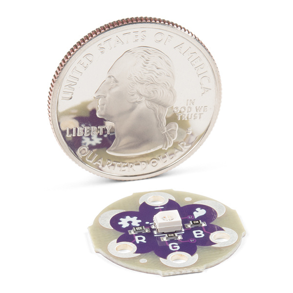
The LilyPad RGB LED is a specialty board that can produce a variety of colors. On the board is an RGB (red-green-blue) LED, made of three tiny LEDs connected together. Each of the colors in the RGB LED are connected to one of the sew tabs on the board labeled R, G, and B.
Required Materials
To follow along with the code examples, we recommend:
Suggested Reading
To add this LED to a project, you should be comfortable sewing with conductive thread and uploading code to your LilyPad Arduino (for the programming examples). Here are some tutorials to review before working with this part:
What is a Circuit?
Every electrical project starts with a circuit. Don't know what a circuit is? We're here to help.
Light
Light is a useful tool for the electrical engineer. Understanding how light relates to electronics is a fundamental skill for many projects.
Insulation Techniques for e-Textiles
Learn a few different ways to protect your conductive thread and LilyPad components in your next wearables project.
LilyPad Basics: E-Sewing
Learn how to use conductive thread with LilyPad components.
Getting Started with LilyPad
An introduction to the LilyPad ecosystem - a set of sewable electronic pieces designed to help you build soft, sewable, interactive e-textile projects.
Note on Common Anode vs Common Cathode
The color channels on this RGB LED are all connected through a common cathode (negative) pin. This configuration means that the individual red, green, and blue LEDs share a common ground tab. To light up each color individual LED, connect them each to a power source. For simple circuit hookups, this means you need to connect the R, G, or B sew tabs to power (+) and in code set them to HIGH (for digital output) or 255 (for analog output) to turn them on.

The RGB LED has 4 connections: red, green, blue channels, and a common cathode pin.
If you look closely you can see the individual LEDs inside the package.
The color channels on this RGB LED are all connected through a common cathode (negative) pin. This configuration means that the individual red, green, and blue LEDs share a common ground tab. To light up each color individual LED, connect them each to a power source. For simple circuit hookups, this means you need to connect the R, G, or B sew tabs to power (+) and in code set them to HIGH (for digital output) or 255 (for analog output) to turn them on.

If you look closely you can see the individual LEDs inside the package.
