LIDAR-Lite v3 Hookup Guide
Troubleshooting
Arduino Output Error Poor Connection
Are you seeing this output from the LIDAR-Lite V3 I2C example code with the decoupling capacitors connected to the Arduino?
> nack
> nack
> nack
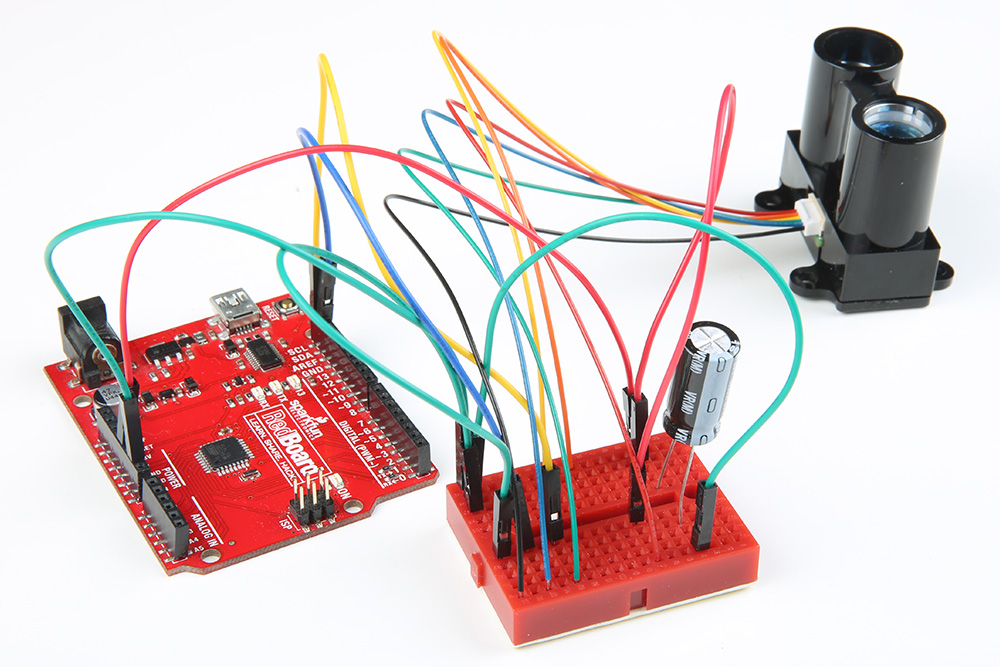
You probably do not have a secure connection between the Lidar and the Arduino. I2C is sensitive to its connection. The cable wires are thin and can disconnect when in the Arduino's female header from a bump. A breadboard seems to work fine if there is not a lot of mechanical vibrations. However, a small bump can mess up the timing for the I2C even on the breadboard.
 |
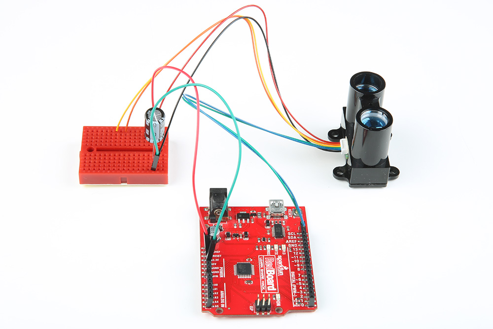 |
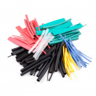
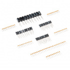
For a secure connection, it is recommended soldering header pins with some heat shrink or make sort of adapter when connecting it to an Arduino. Once disconnected, the Arduino might stop outputting sensor data. You can reset the Arduino for testing but to prevent the wires from disconnecting, it would be better to solder the wires to header pins. This is a common "issue" with any I2C sensor and if they do not secure the wires, the Arduino will have problems talking with the Lidar Lite V3.
Arduino Output Error I2C Pull-Up Resistors
Another reason for the nack error may be that you need I2C pull-up resistors for the SCL and SDA lines. It depends on the length between the Arduino and I2C device but usually a 4.7kΩ resistor is a good start. For long runs or systems with lots of devices, it is recommended to use smaller resistors. You can also use a I2C bus extender for distances beyond the maximum bus length as well.
Decoupling Capacitor
Looking for a 680µF capacitor? Unfortunately, the SparkFun catalog does not include a 680µF capacitor. There are 1000µF capacitors, which can work as a substitute with the Lidar Lite.
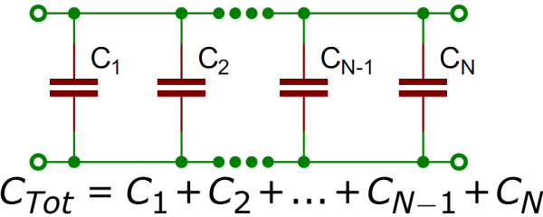
Or, you can also wire capacitors in series and parallel to get an equivalent capacitance.
 |
Dimensions
For more details on the dimensions, check out the links below.
Product Showcase Example for LIDAR-Lite V3 Wand
Looking for the example code used in the product video for the LIDAR-LIte V3? Nick Poole basically used the same parts and example code that was used with the Lidar Lite V2 Glasses. For the Lidar Lite V3 Wand, he used the following components:
- LEDs
- micro-B USB breakout
- micro-B USB Cable
- a backup portable cell phone charger
- 1kΩ resistor
- 5V/16 MHz Pro Micro
He happened to have a 5V/16 MHz Pro Micro around when building the project for the Lidar Lite V2 Glasses. The parts were reused for the Lidar Lite V3 Wand. Try looking at the old wishlist for the Lidar Lite V2 Glasses for more information. Make sure to also add a 1kΩ resistor when using the PWM wiring as stated on page 3 of the user manual.
Additional Troubleshooting
Looking for additional troubleshooting tips and application notes related to the LIDAR Lite? Check out Garmin's support on the LIDAR Lite:
Application Notes on Reflective Surfaces
For more application notes on using the LIDAR-Lite v3/v3HP, check out the link below.
This can also be found in the operation & technical manual on page 11.

