Large Digit Driver Hookup Guide
Contributors:
 Shawn Hymel
Shawn Hymel 
Example: One Large Digit
Note: This example assumes you are using the latest version of the Arduino IDE on your desktop. If this is your first time using Arduino, please review our tutorial on installing the Arduino IDE.
If you have not previously installed an Arduino library, please check out our installation guide.Load the Single Digit Example Code
Plug your Arduino into your computer via USB cable. Open up the Arduino program and copy in the following sketch.
language:c
/*
Controlling large 7-segment displays
By: Nathan Seidle
SparkFun Electronics
Date: February 25th, 2015
License: This code is public domain but you buy me a beer if you use this and we meet someday (Beerware license).
The large 7 segment displays can be controlled easily with a TPIC6C594 IC. This code demonstrates how to control
one display.
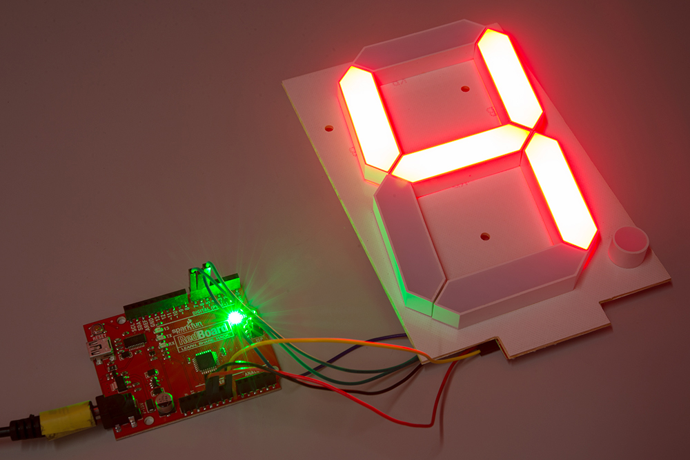
Here's how to hook up the Arduino pins to the Large Digit Driver
Arduino pin 6 -> CLK (Green on the 6-pin cable)
5 -> LAT (Blue)
7 -> SER on the IN side (Yellow)
5V -> 5V (Orange)
Power Arduino with 12V and connect to Vin -> 12V (Red)
GND -> GND (Black)
There are two connectors on the Large Digit Driver. 'IN' is the input side that should be connected to
your microcontroller (the Arduino). 'OUT' is the output side that should be connected to the 'IN' of addtional
digits.
Each display will use about 150mA with all segments and decimal point on.
*/
//GPIO declarations
//-=-=-=-=-=-=-=-=-=-=-=-=-=-=-=-=-=-=-=-=-=-=-=-=
byte segmentClock = 6;
byte segmentLatch = 5;
byte segmentData = 7;
//-=-=-=-=-=-=-=-=-=-=-=-=-=-=-=-=-=-=-=-=-=-=-=-=
void setup()
{
Serial.begin(9600);
Serial.println("Large Digit Driver Example");
pinMode(segmentClock, OUTPUT);
pinMode(segmentData, OUTPUT);
pinMode(segmentLatch, OUTPUT);
digitalWrite(segmentClock, LOW);
digitalWrite(segmentData, LOW);
digitalWrite(segmentLatch, LOW);
int x = 0;
while(1)
{
if(x == 9)
postNumber(x, true); //Show decimal
else
postNumber(x, false);
digitalWrite(segmentLatch, LOW);
digitalWrite(segmentLatch, HIGH); //Register moves storage register on the rising edge of RCK
delay(500);
x++;
x %= 10; //Reset x after 9
Serial.println(x); //For debugging
}
}
void loop()
{
//showNumber(42); //Test pattern
}
//Takes a number and displays 2 numbers. Displays absolute value (no negatives)
void showNumber(float value)
{
int number = abs(value); //Remove negative signs and any decimals
//Serial.print("number: ");
//Serial.println(number);
for (byte x = 0 ; x < 2 ; x++)
{
int remainder = number % 10;
postNumber(remainder, false);
number /= 10;
}
//Latch the current segment data
digitalWrite(segmentLatch, LOW);
digitalWrite(segmentLatch, HIGH); //Register moves storage register on the rising edge of RCK
}
//Given a number, or '-', shifts it out to the display
void postNumber(byte number, boolean decimal)
{
// - A
// / / F/B
// - G
// / / E/C
// -. D/DP
#define a 1<<0
#define b 1<<6
#define c 1<<5
#define d 1<<4
#define e 1<<3
#define f 1<<1
#define g 1<<2
#define dp 1<<7
byte segments;
switch (number)
{
case 1: segments = b | c; break;
case 2: segments = a | b | d | e | g; break;
case 3: segments = a | b | c | d | g; break;
case 4: segments = f | g | b | c; break;
case 5: segments = a | f | g | c | d; break;
case 6: segments = a | f | g | e | c | d; break;
case 7: segments = a | b | c; break;
case 8: segments = a | b | c | d | e | f | g; break;
case 9: segments = a | b | c | d | f | g; break;
case 0: segments = a | b | c | d | e | f; break;
case ' ': segments = 0; break;
case 'c': segments = g | e | d; break;
case '-': segments = g; break;
}
if (decimal) segments |= dp;
//Clock these bits out to the drivers
for (byte x = 0 ; x < 8 ; x++)
{
digitalWrite(segmentClock, LOW);
digitalWrite(segmentData, segments & 1 << (7 - x));
digitalWrite(segmentClock, HIGH); //Data transfers to the register on the rising edge of SRCK
}
}
Run
Upload the sketch to your Arduino, and plug the 12V adapter into the Arduino.

Flip the 7-segment display over. You should see it count the digits 0-9 (the decimal point will appear on 9).