Large Digit Driver Hookup Guide
 Shawn Hymel
Hardware Hookup
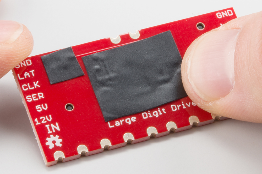
Protect the Board
Before you attach the Large Digit Driver to the 7-segment display, you will need to isolate the exposed vias on the back of the board. Some of the Driver boards are created with through-hole vias that are not covered with solder mask. As a result, this could likely short out the traces on the back of the 7-segment display.
We recommend using a piece of electrical tape or high temperature tape to cover the vias on the back of the Driver board.
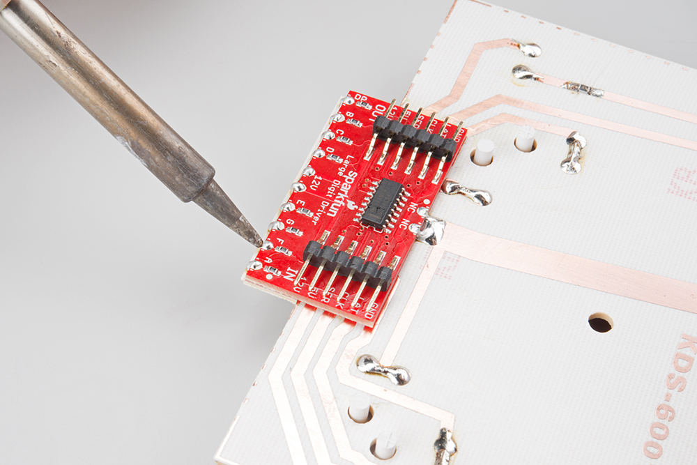
Attach the Board
You will need to solder the Large Digit Driver to the back of the 7-segment display. Have the Driver's 10 pins facing toward the bottom of the large 7-segment display and lined up with the traces on the back of the 7-segment display. Follow the Soldering Castellated Vias Guide to solder all 10 of the castellations as well as the 2 castellations at the top of the board (these should be attached to the 12V line and are just for mechanical support).
Connect the Board
We will be using the Arduino's regulated 5V and unregulated 12V (from the wall adapter) to power the 7-segment display and Large Digit Driver.
Connect the Large Digit Driver to the the following pins on the Arduino.
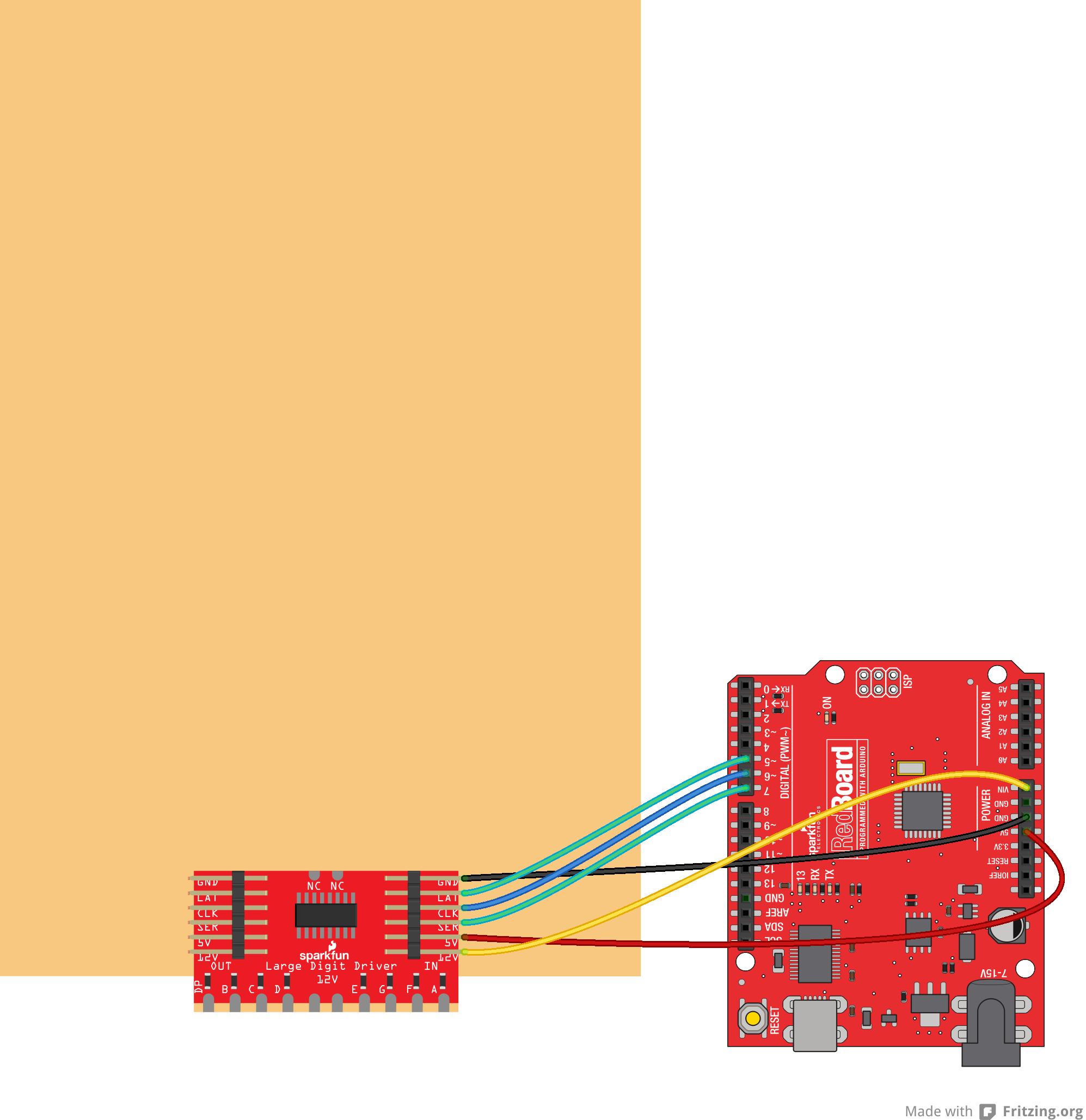
| Large Digit Driver | Arduino |
|---|---|
| GND | GND |
| LAT | 5 |
| CLK | 6 |
| SER | 7 |
| 5V | 5V |
| 12V | VIN |