Large Digit Driver Hookup Guide
Contributors:
 Shawn Hymel
Shawn Hymel 
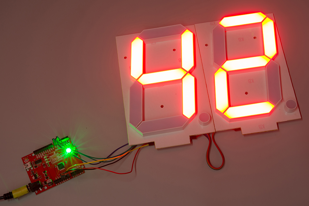
Example: Two Large Digits
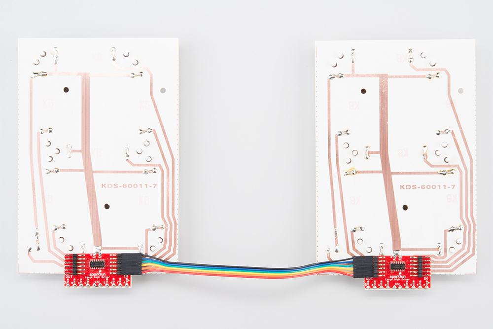
Attach a Second Digit
Use the 6-pin jumper wire to attach a second 7-segment display to the first display unit. Make sure that you connect GND of the OUT on the first display to the GND of the IN on the second display, LAT of the OUT on the first display to the LAT of the IN on the second display, and so on.
You will want to connect the Large Digit Driver on the right to the Arduino as per the Hardware Hookup section.
Load the Two Digit Example Code
Make sure the Arduino is plugged into your computer using a USB cable. Copy the following sketch into the Arduino program.
language:c
    /*
 Controlling large 7-segment displays
 By: Nathan Seidle
 SparkFun Electronics
 Date: February 25th, 2015
 License: This code is public domain but you buy me a beer if you use this and we meet someday (Beerware license).

 This code demonstrates how to post two numbers to a 2-digit display usings two large digit driver boards.

 Here's how to hook up the Arduino pins to the Large Digit Driver IN

 Arduino pin 6 -> CLK (Green on the 6-pin cable)
 5 -> LAT (Blue)
 7 -> SER on the IN side (Yellow)
 5V -> 5V (Orange)
 Power Arduino with 12V and connect to Vin -> 12V (Red)
 GND -> GND (Black)

 There are two connectors on the Large Digit Driver. 'IN' is the input side that should be connected to
 your microcontroller (the Arduino). 'OUT' is the output side that should be connected to the 'IN' of addtional
 digits.

 Each display will use about 150mA with all segments and decimal point on.

*/

//GPIO declarations
//-=-=-=-=-=-=-=-=-=-=-=-=-=-=-=-=-=-=-=-=-=-=-=-=
byte segmentClock = 6;
byte segmentLatch = 5;
byte segmentData = 7;

//-=-=-=-=-=-=-=-=-=-=-=-=-=-=-=-=-=-=-=-=-=-=-=-=

void setup()
{
  Serial.begin(9600);
  Serial.println("Large Digit Driver Example");

  pinMode(segmentClock, OUTPUT);
  pinMode(segmentData, OUTPUT);
  pinMode(segmentLatch, OUTPUT);

  digitalWrite(segmentClock, LOW);
  digitalWrite(segmentData, LOW);
  digitalWrite(segmentLatch, LOW);
}

int number = 0;

void loop()
{
  showNumber(number); //Test pattern
  number++;
  number %= 100; //Reset x after 99

  Serial.println(number); //For debugging

  delay(500);
}

//Takes a number and displays 2 numbers. Displays absolute value (no negatives)
void showNumber(float value)
{
  int number = abs(value); //Remove negative signs and any decimals

  //Serial.print("number: ");
  //Serial.println(number);

  for (byte x = 0 ; x < 2 ; x++)
  {
    int remainder = number % 10;

    postNumber(remainder, false);

    number /= 10;
  }

  //Latch the current segment data
  digitalWrite(segmentLatch, LOW);
  digitalWrite(segmentLatch, HIGH); //Register moves storage register on the rising edge of RCK
}

//Given a number, or '-', shifts it out to the display
void postNumber(byte number, boolean decimal)
{
  //    -  A
  //   / / F/B
  //    -  G
  //   / / E/C
  //    -. D/DP

#define a  1<<0
#define b  1<<6
#define c  1<<5
#define d  1<<4
#define e  1<<3
#define f  1<<1
#define g  1<<2
#define dp 1<<7

  byte segments;

  switch (number)
  {
    case 1: segments = b | c; break;
    case 2: segments = a | b | d | e | g; break;
    case 3: segments = a | b | c | d | g; break;
    case 4: segments = f | g | b | c; break;
    case 5: segments = a | f | g | c | d; break;
    case 6: segments = a | f | g | e | c | d; break;
    case 7: segments = a | b | c; break;
    case 8: segments = a | b | c | d | e | f | g; break;
    case 9: segments = a | b | c | d | f | g; break;
    case 0: segments = a | b | c | d | e | f; break;
    case ' ': segments = 0; break;
    case 'c': segments = g | e | d; break;
    case '-': segments = g; break;
  }

  if (decimal) segments |= dp;

  //Clock these bits out to the drivers
  for (byte x = 0 ; x < 8 ; x++)
  {
    digitalWrite(segmentClock, LOW);
    digitalWrite(segmentData, segments & 1 << (7 - x));
    digitalWrite(segmentClock, HIGH); //Data transfers to the register on the rising edge of SRCK
  }
}
Run
Upload the sketch to your Arduino, and plug in the 12V supply. The 7-segment display (now two digits!) should count from 00 to 99.