ITG-3200 Hookup Guide
 Joel_E_B,
  zagGrad
Hooking it Up
There are only two considerations for assembling the ITG-3200 breakout: what to do for the headers, and whether or not you're going to use an external clock source for the ITG-3200.
For the headers you have a couple options, you can solder in male or female 0.1" headers, or you can just solder wires directly to the holes in the breakout board. In this example, male headers are soldered to the breakout board to make it easy to attach to a breadboard. Then, we'll be hooking the ITG-3200 up to an Arduino Leonardo using some male-to-male jumper wires.
Second, since we will not be using an external clock source in this setup, make sure the CLKIN jumper on the bottom of the ITG-3200 is closed with a blob of solder.
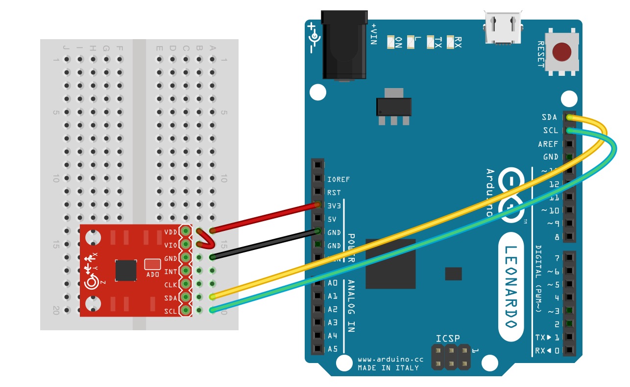
The SDA and SCL pins should be present on most Arduinos. Older, pre-rev3 Arduinos might not have SCL and SDA pins. In that case, connect SDA to A4 and SCL to A5.
The ITG3200 sensor is a 3.3V device. This means that the sensor should be powered by 3.3V and the communication signals should be between 0V and 3.3V. The Arduino Leonardo (and other similar boards) are 5V devices. Even though we power the board with the 3.3V output from the Arduino, the communication signals are still going to be 5V. Technically this should be avoided as it can cause damage to the sensor in the long run. When implementing this gyro in a final project, it's in your best interest to use something like a Logic Level Converter to change the voltages of the communication signals. You could also use an Arduino Pro (3.3V/8 MHz). However, for the purposes of testing out your gyro, using a 5V device should work fine.
That's all there is to it! Now, let's look at some code to get this gyro up and running.