ITG-3200 Hookup Guide
 Joel_E_B,
  zagGrad
Hardware Overview
Power
The ITG-3200 can be powered at anywhere between 2.1 and 3.6V. For power supply flexibility, the ITG-3200 has a separate VLOGIC reference pin (labeled VIO), in addition to its analog supply pin (VDD), which sets the logic levels of its serial interface. The VLOGIC voltage may be anywhere from 1.71V min to VDD max. For general use, VLOGIC can be tied to VCC. The normal operating current of the sensor is just 6.5mA.
Communication
Communication with the ITG-3200 is achieved over a two-wire (I2C) interface. The sensor also features a interrupt output and an optional clock input.
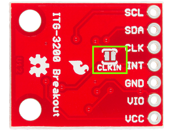
Clock Source Jumper
In the next picture, you can see a small jumper next to the pin labeled 'CLK.' The ITG-3200 has a feature that allows you to connect an external clock. Unless you plan to use an external clock, you need to 'close' this jumper by connecting the two pads with solder. If you're following this tutorial and using the provided example code, go ahead and close the jumper.
I2C Address Jumper
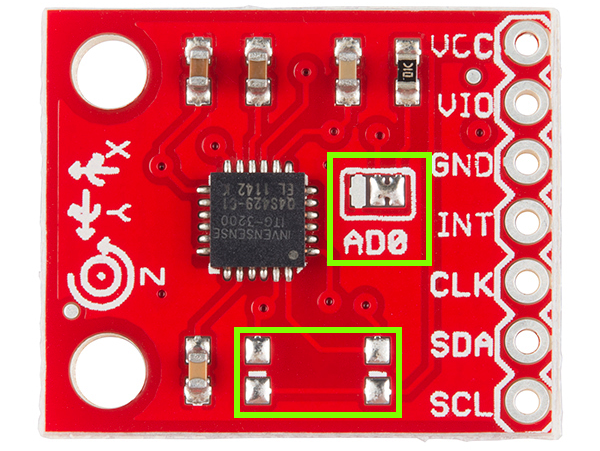
A jumper on the top of the board allows you to easily select the I2C address, by pulling the AD0 pin to either VCC or GND; the board is shipped with this jumper tied to VCC.
I2C Pull-up Resistors
Note that there are two unpopulated pull-up resistors on the I2C lines. These can be added later by the user if desired.