IoT Industrial Scale
 jenfoxbot
Build the Electronics
Schematic:
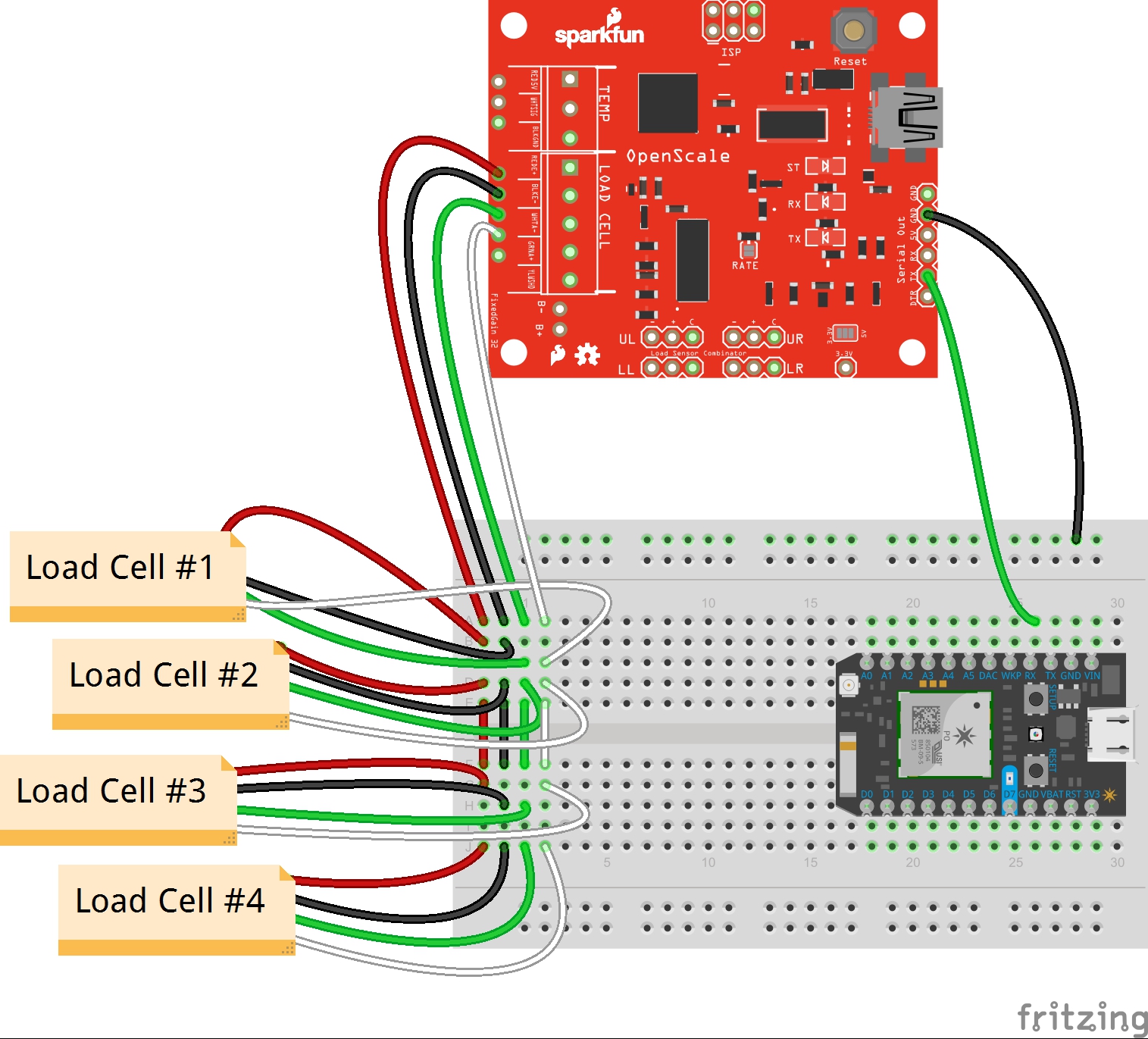
Part 1: Connect the Load Cells!

Load cells have four signal wires:
- Red: Excitation+ (E+) or VCC
- Black: Excitation- (E-) or ground
- White: Output+ (O+), Signal+ (S+)+ or Amplifier+ (A+)
- Green (or blue): Output- (O-), Signal- (S-), or Amplifier (A-)
They also have bare (or yellow) grounding wires to block outside (electromagnetic) noise.
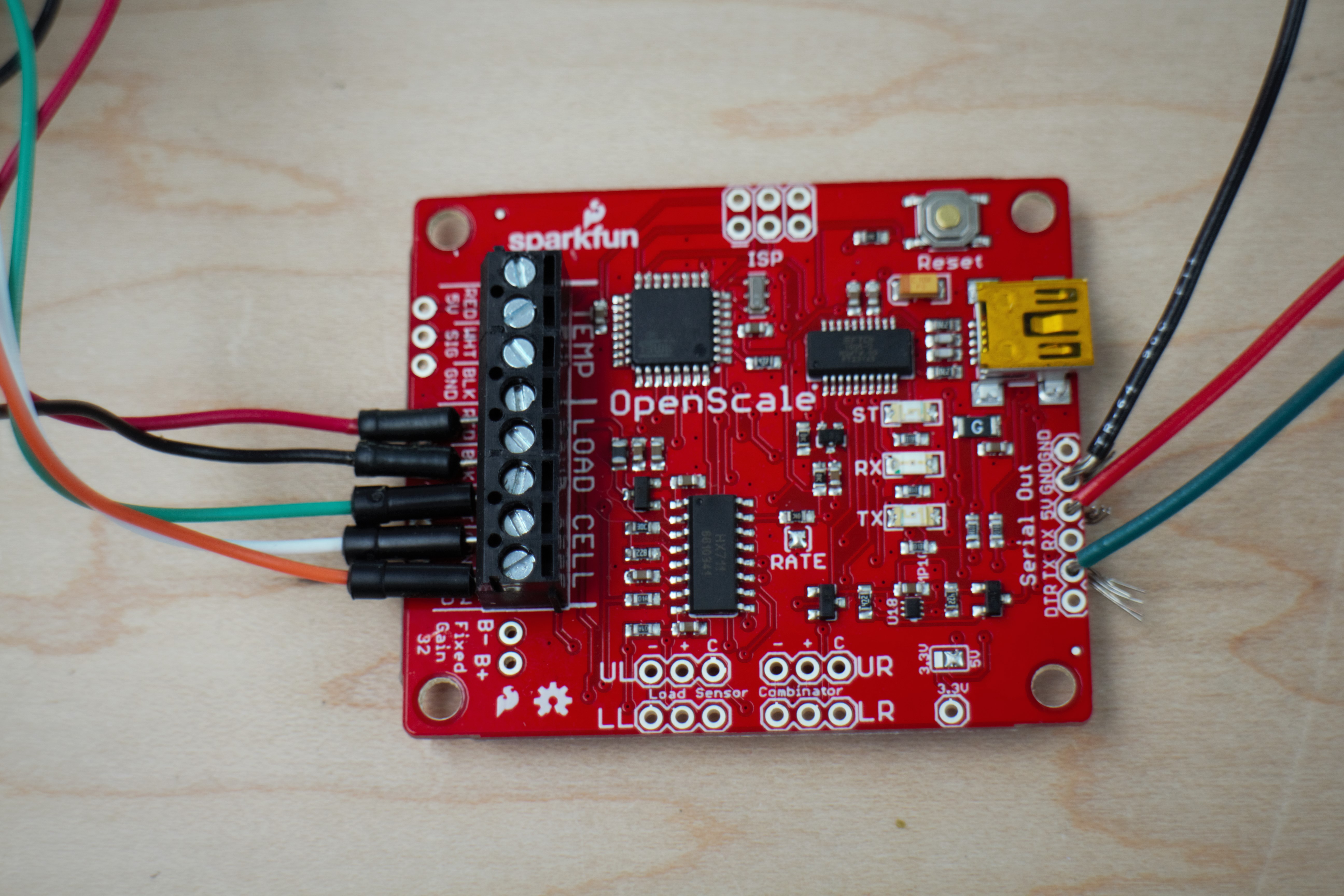
Connect all five load cell wires in parallel to the OpenScale terminal blocks with the corresponding labels. You might need to switch the green and white load cell wires -- check this by adding weight to the load cells. If the weight is decreasing, switch the wire orientation.
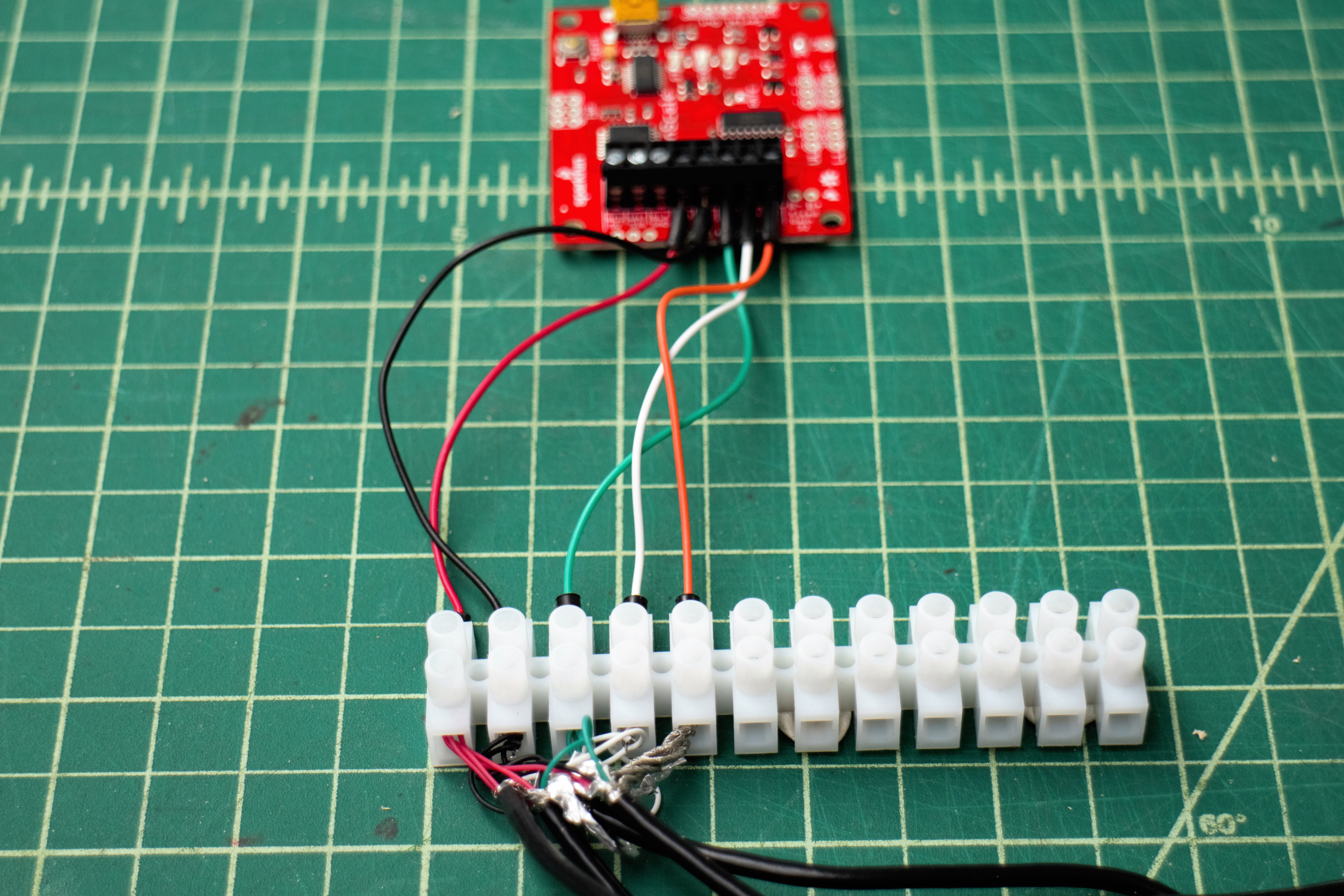
Since the OpenScale terminal blocks are somewhat cramped with four load cells, external connectors are recommended. I used the terminal blocks pictured above. If you have a case for the electronics, remember to put the connectors INSIDE the case before connecting them to the load cells (not speaking from experience or anything..).
Part 2: Connect the OpenScale to a Data Logger!
In addition to printing, reading, and gathering data from the Arduino serial monitor (see "Reading Load Cells!"), we can add a Photon microcontroller to connect to WiFi and upload the measurements to the Internet!
Connect the OpenScale "Serial Out" ground ("GND") port to the Photon GND, and the OpenScale "TX" port to the Photon "RX" port. If your data logger needs power, connect the OpenScale 5V port to the data logger Vin port. That's it!