Interactive Hanging LED Array
 Nick Poole
Intro to Installation Art
This is not your intro to installation art... but it was my intro to installation art. What started as a conspiracy between myself and our videographer to do something big and impressive for SparkFun slowly became a PWM controlled, 72 channel, music-reactive, albatross around my neck. But, in the end, the payoff was totally worth it, and the experience of completing a whole-room project is, I would argue, an essential experience for any maker.
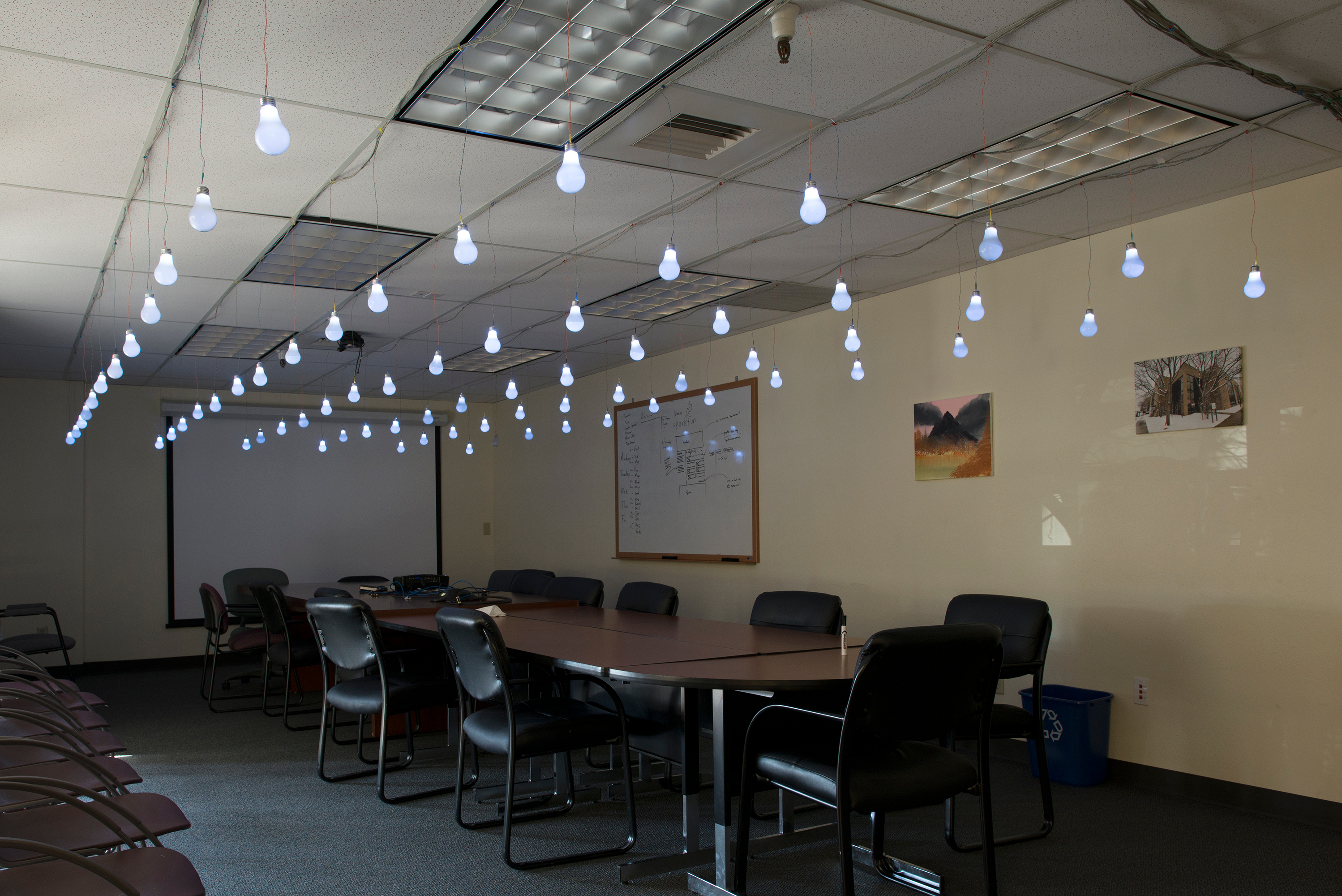
Let me share with you the process, plans, and source materials behind my effort to turn one of SparkFun's conference rooms into a 6x12 interactive LED matrix. That may not sound like a big matrix but when you're standing in the middle of it... it's pretty cool.
Suggested Reading
If you'd like to follow along at home, here are some topics you'll need to be familiar with before diving into this project:
72 Lightbulbs
Originally, the idea was that we would hang unaltered, incandescent light bulbs from the ceiling and control them using a bank of relays. A few experiments proved that this was easier said than done. The trick with an array of anything is that the effort necessary to get one piece working is multiplied into near impossibility. In this case, whatever it takes to get one light up and running will need to be repeated 72 times to complete the 6x12 grid.
There are a few major problems surrounding regular light bulbs. First of all, they are not terribly efficient, and the power requirement for lighting 72 bulbs at once (even at just 15 or 20 Watts a piece) can be daunting. Secondly, you get no brightness control, which limits the number of cool things that the installation can do. Finally, running that much high voltage line across the ceiling made us all nervous.
Eventually we settled on LEDs. They're low voltage, relatively low power, and their brightness can be controlled with PWM. The only problem with LEDs is that they're tiny, so they don't look very interesting hanging from the ceiling and don't have enough weight to hang plumb because the wire has a tendency to coil. We played with different ways of encasing LEDs in plastic and glue to make them more visually appealing, but we really wanted them to look like light bulbs. Our final decision was to hollow out 72 real light bulbs and replace their guts with LEDs.
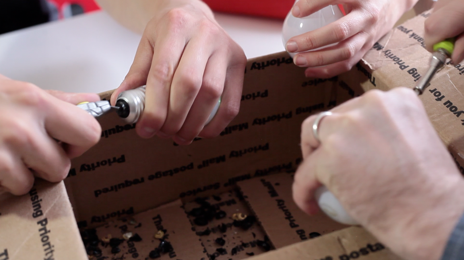
Light bulbs aren't really meant to be taken apart once they've been put together, so it's a little bit of a challenge to get into them. I enlisted the help of some coworkers, and we started pulling the ceramic insulators out of all of the bulbs, one box at a time. I didn't break the envelope of the bulbs (the sealed part) because I hoped that the intact glass stem would help diffuse the LED light. Then I set about filling each bulb's stem with hot glue and setting LEDs in place.
As I made my way through the boxes of bulbs, I tested each one with a coin cell battery to be sure the LEDs were good, then I put them back in their boxes and set those aside. My next task would be determining how to individually control 72 LEDs with as little headache as possible...
Everything's Under Control
There are a lot of ways to control a whole heap of LEDs. Multiplexing is a nice way to conserve GPIO, but even if you multiplex 72 LEDs you still need 9 pins to do it. I really wanted to use an Arduino Pro Mini for my controller, however that didn't leave many pins open for sensors and other fun stuff. A couple of shift registers would be a decent way to individually control all of the LEDs if all I wanted to do is turn them on or off. I really want varying levels of brightness, though.

In the end, the best tool for the job was the TLC5940 PWM Driver. The TLC5940 is capable of running 16 channels of PWM at a resolution of 12-bits! That's 4096 levels of brightness! Best of all, they can be daisy-chained together so that it takes the same amount of IO pins to control 16 LEDs as it does to control 72. I simply soldered 5 of our TLC5940 breakout boards into a line and connected each LED to its very own PWM channel.
Doing all of the computation for this installation was the Arduino Pro Mini. This is my favorite Arduino board because of its compact size, not that I really needed to save space, but I had a few of these hanging around. I went ahead and soldered right-angle headers onto the board for an FTDI, which I ended up leaving connected in the enclosure.
Powering the operation was yet another challenge. Some things wanted 3V, some wanted 5V and I needed enough power to light 72 super bright LEDs at once. There was really only one tool for that job, and it's the good old computer PSU. Power Supplies from old PCs make excellent voltage sources for projects like this because they're self-contained, regulated, and can source quite a bit of current. They also output all of the common voltage levels you'll need: 12, 5 and 3.3VDC! To get a PSU to run without being connected to a motherboard, you'll need to find the enable wire and tie in to ground. Usually it's the green wire in the large connector.
All of the power and control components needed a place to live, so I built a simple cabinet out of OSB. There's a power outlet in a juntion box inside the cabinet, which is wired to the light switch on the front. This allows me to keep all of the power cables inside the cabinet and bring the whole thing up with one switch. For added flair I stained the OSB and bent some custom cabinet legs out of flatstock.

Once the control cabinet was erected, the time had come to do the hard work: Wiring 72 LEDs individually and hanging them from the ceiling...
On Running Cable
Because I wanted to hang the lights in an array on the ceiling, each LED needed to be on a separate length of wire running from its position on the ceiling to the control cabinet. That's a problem for a couple of reasons, not least of which is the sheer amount of wire needed to make that stretch. I started by selecting a good multi-conductor cable. I figured it would be easier to strip some sort of ribbon cable and drop the LED lines at intervals from the main ribbon than it would be to run 144 separate wires and bundle them later. After looking around for multi-conductor cable that can be bought in bulk, I finally settled on networking cable!
As it turns out, a 1000ft. box of CAT5 networking riser will wire just about anything and everything you need. And, because networking cable is made up of twisted pairs, it's perfect for wiring LEDs. In an ideal world, I could have taken that box of wire and just started draping wire from the ceiling to get things cut correctly. Unfortunately, in the real world, this was getting installed in a conference room, so I couldn't really set up shop.
Since I was working on a drop ceiling, I decided to make the grid of the LED matrix on 2 foot centers. Because I knew that and the fact that I wanted about 2 feet of drop from the ceiling, I was able to plan all of my cable runs and build them in my office before installing them. I started by organizing the LEDs into rows and columns, then finding out what length of cable was required from the control cabinet to the end of each column. That "lead length" was added to the beginning of each cable stretch, and then I made a mark every 2' after that for 24'. I stripped the cable back to the point of the first LED drop, cut one of the twisted pairs at that point, and soldered the LED to it. Finally, each LED drop got a zip tie to keep the cables bundled. Each column became its own roll of wire and LEDs that I could just haul over to the conference room and hang in a few hours... not without some help.
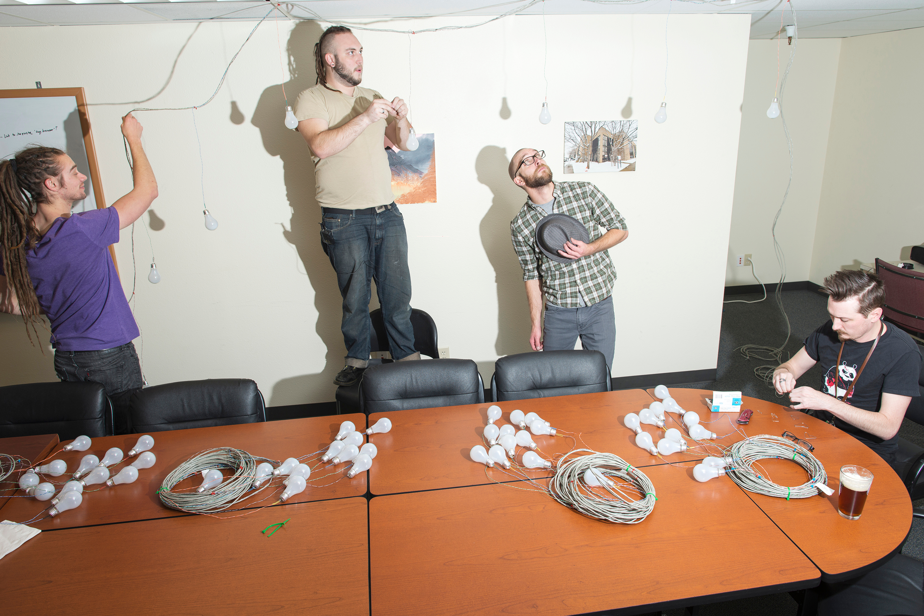
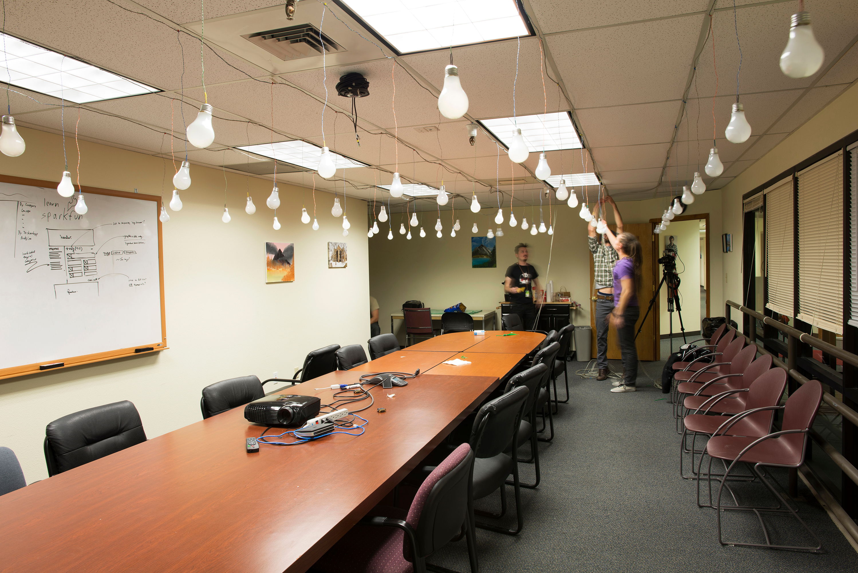
On the night of the installation there were a handful of us running wires around the conference room, and a couple of people recording the event for posterity. Instead of trying to find actual ceiling hooks, we snagged a box of paper clips from the supply closet and bent them into hook shapes. It actually worked fairly well. Many hands made fast work, and, much to my surprise, all of the bulbs lined up and I had more than enough cable to reach the control cabinet.
After doing this project I learned a few lessons in building wiring harnesses. All of which I will gladly share with you now:
Measure Twice, Cut Once - Yep, an oldie but a goodie. There's nothing worse than ruining a 40' wiring harness by chopping 6" off the wrong conductor.
Leave Some Slop - Okay, even if you're 100% sure that you've made the right measurements, throw an extra bit of length on there. I added about 6" extra to all of my lines to allow for silly things like accidentally cutting a wire instead of stripping it.
Rubber Bands, Zip Ties, and Wire Loom - Cable management hardware is essential, while I have been known to simply tie knots in cables to keep them together this method has a few downsides including the overall shortening of the cable. You can never have too many wire ties.
Spare a Thought for Resistance - Just ask any Power Engineer, even copper wire will introduce significant resistance given a long enough stretch. Measure the resistance of your wiring harnesses and account for any voltage drop. If you're doing a high power project, whip out your Ohm's Law calculator, and make sure you aren't driving too much current through the wire.
Spread the Work Out - Get some friends, or, if you're not on a tight deadline, you can do it yourself in chunks. Stripping and bundling wire is the kind of thing that you can burn out on really quickly, and, if you try to finish it all in one stretch, you could make the kinds of mistakes that are hard to track down post-install.
Label Ev-er-y-thing! - Same deal as wire ties, you can't have too many labels. Create a color code, write it down, take pictures, wrap everything in masking tape, and label it with markers. Just make sure once you're done, you know which wire on end A connects to which wire on end B.
That's most of the infrastructure installed. Once I had the power and control cabinet built and the lightbulbs were in the air, all I needed was some kind of data for the installation to react to...
Interactivity
A whole bunch of lights in a grid is not a boring thing, but, if it doesn't react to its environment, you've basically just made a huge, mega-low resolution television display. I decided to create a few different modes to allow the installation to react and respond in different ways. The nice thing about programmable microcontrollers, like the Arduino's ATmega328, is that you can very quickly write and test a lot of firmware without even touching your hardware layout.
I spent a few days just writing new sketches and hooking up new sensors to play with ideas and find out what the most engaging and stable types of interaction would be. At one point I used blinking lights to entice people to walk within range of a sensor, which would then alert them to their effect on the lights, but not everyone's reaction to blinking lights is the same. I also wrote a whole bunch of simple animations for the display, just sweeping lines of light around the room or creating the illusion of flashing fireflies.
My favorite experiments used ultrasonic range finders as an input device. Ultrasonics are nice and stable and aren't affected by changes in ambient light, they also have a long enough range and wide enough detection zone to work as general activity monitors if they're strategically placed. I decided to add 2 Maxbotix Range Finders to the installation, on either end of the conference room. Each one would run to a different ADC on the Arduino so I could read them quickly and independently. I simply taped them to the wall with a bit of foam tape; they're so small you hardly notice them.
My favorite application of the range finders was for playing pong. I built a single player pong game that could be played by moving back and forth along the side of the playing field. There are only three paddle positions, but they map really closely to which lightbulbs you're standing underneath. The game is actually pretty fun and fast paced.
Along with the range finders, I wanted some kind of sounds interaction. Unfortunately, ambient sound reaction is hit or miss. Our brains are so good at filtering sound that we often don't realize how noisy a room is until we ask a computer to monitor it. The difference between a "quiet" room and a meeting might be more in the frequency spectrum than the actual loudness level. I really wanted to get one of our Spectrum Shields into the project, though, because creating a music visualizer is so easy and rewarding for big displays. I decided to take a clean music source as the input. At first it was a direct line from the headphone jack on the device, but I later decided to add Bluetooth audio.
Bluetooth connectivity came courtesy of the RN-52 Audio Bluetooth Breakout, which made it pretty easy to get up and running. There's a great hookup guide on our site that explains how to use the RN-52 as a bluetooth boombox, and that's pretty much what I did.
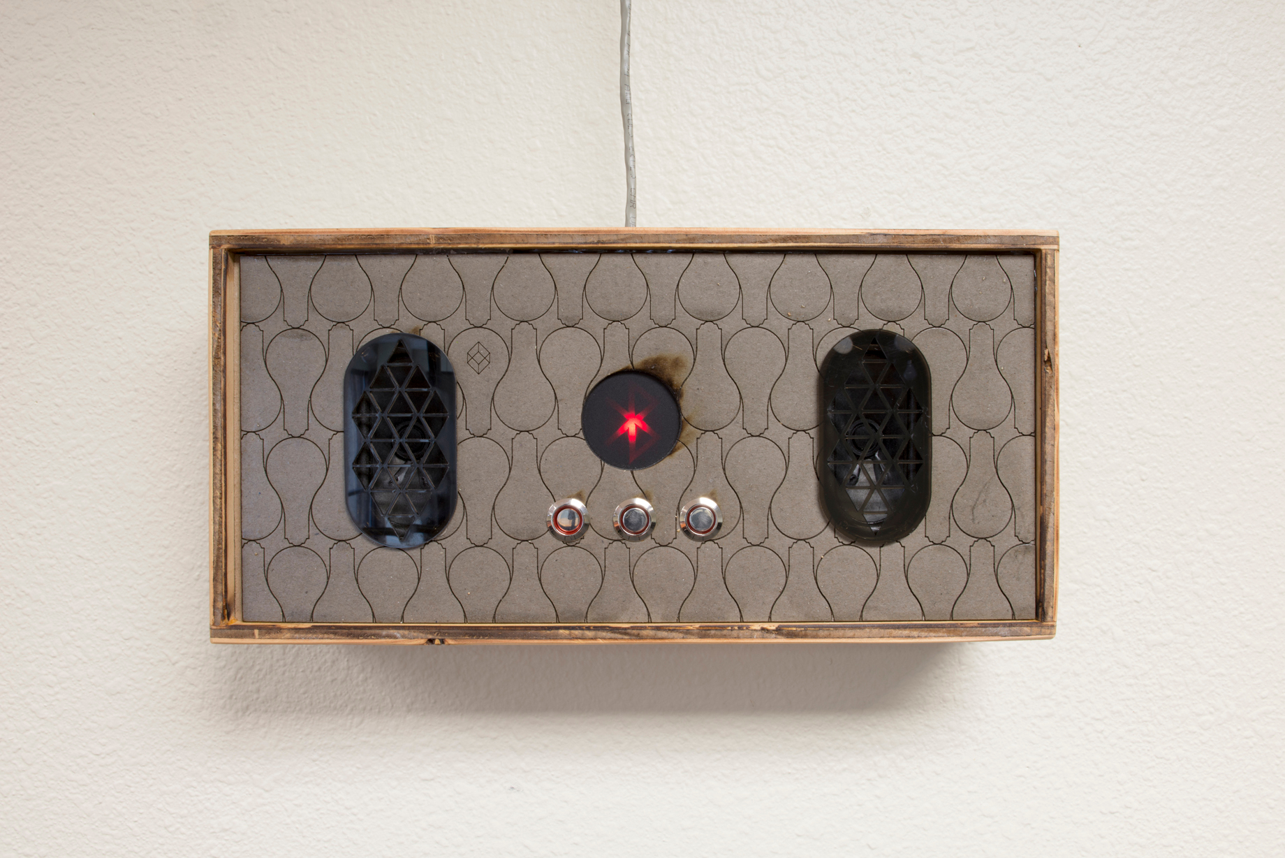
I made an enclosure for the Bluetooth audio portion of the installation, which houses a couple of speakers as well as a few buttons for user input and a Bluetooth status LED. I hung the enclosure on the wall where it would be easy to see and manipulate and ran a cable back to the control cabinet for power. That cable also carried an audio signal from one of the speakers to a Spectrum Shield, which I wired to the 3V Pro Mini using a Logic Level Converter.
All Together Now
Hardware
What? You want more technical details? Well, I've got your technical details right here! Let's do the hardware first so that when we get to the code, you'll have an idea where things are connected:
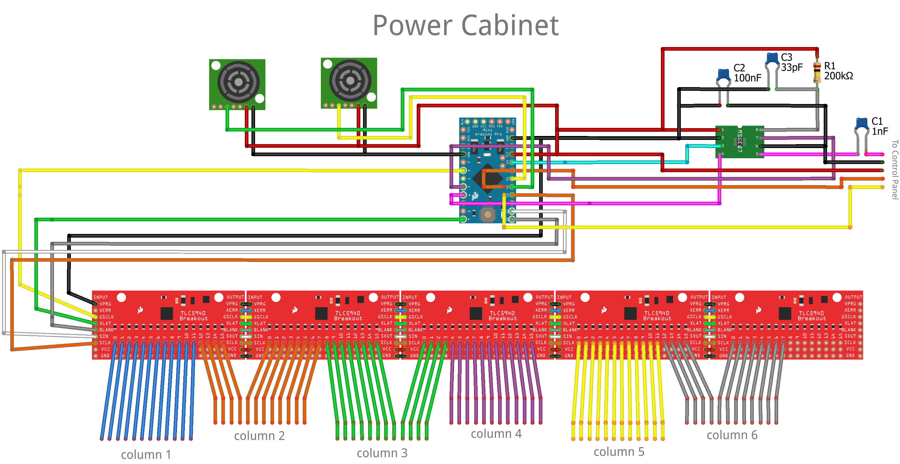
Above, you can see the hardware that we discussed in the Everything's Under Control section. In the above schematic I replaced the spectrum shield with a standalone MSGEQ7 and a handful of passives and got rid of the logic level converter. The shield will work just as well, but you're only using one of two on-board MSGEQ7s. It seemed wasteful.
You can also see that daisy-chaining the TLC5940 Breakout Board is dead easy and gives you a massive amount of control. It can be hard to tell the position of the Arduino analog connections, so here's a list:
- Ultrasonic Range Finders are connected to A0 and A1
- Momentary Pushbuttons are connected to A6 and A7
- DC Out from the MSGEQ7 goes to A3
The group of wires labeled "To Control Panel" are color coded to match the diagram below, so you can follow the connections from one drawing to the other.
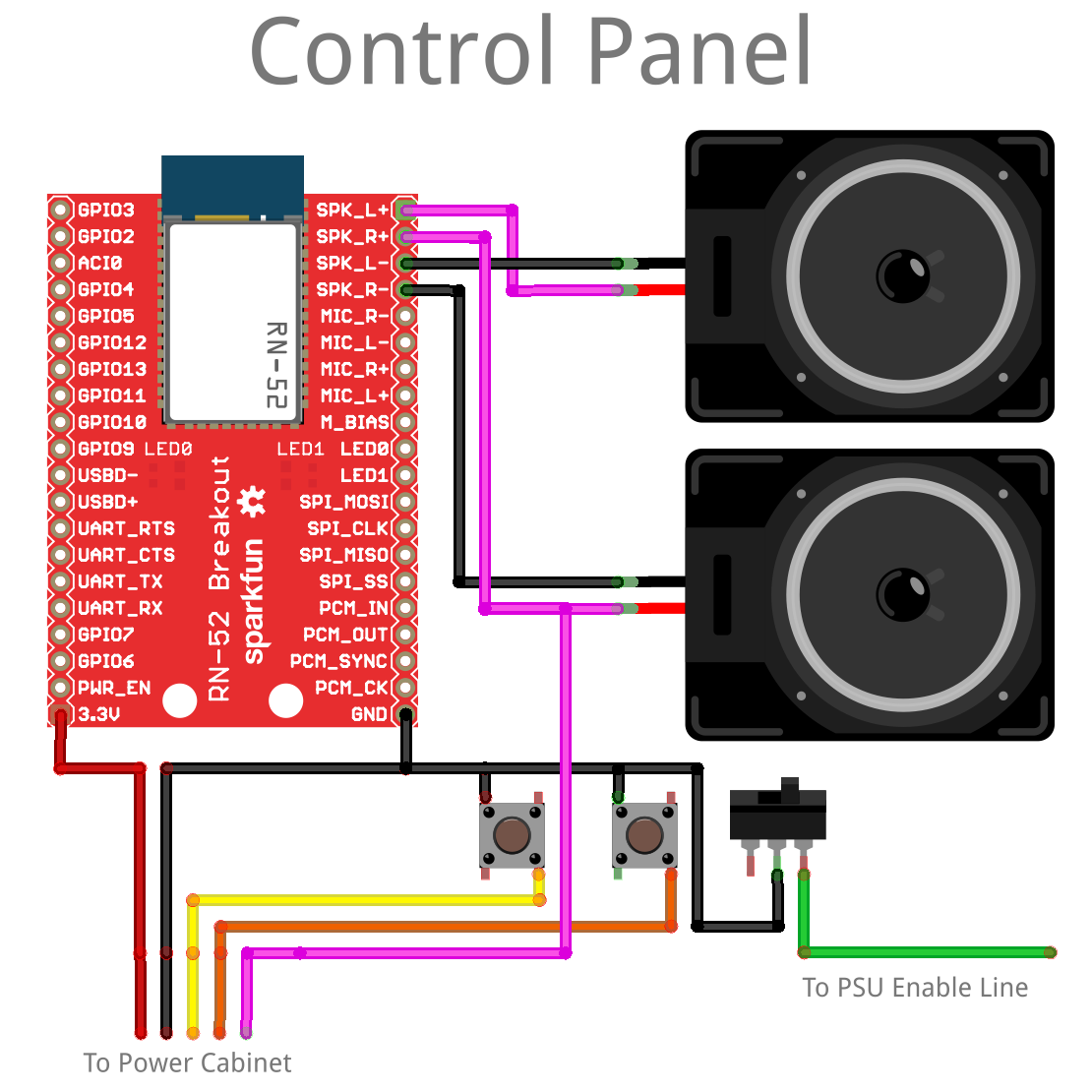
This is the control panel from the Interactivity section. There isn't a whole lot happening. The RN-52 Audio Bluetooth Breakout is doing most of the work. The audio output is differential, so, in order to feed it to the MSGEQ7, I just grabbed the positive side of one speaker and ran with it.
The line that's labeled "To PSU Enable Line" is a power switch for the whole project. It connects that green wire I told you about from the PSU to ground.
Firmware
Okay, now that we've reviewed the hardware, let's dive into the firmware. Are you ready? Too bad, we're doing it anyway!
In order to compile the code, you'll need the TLC5940 library. Let's inspect one piece of the code at a time:
language:c
#include "Tlc5940.h"

//LED Matrix Stuff

int pixel[12][6] = { //locations of LED channels in meatspace
  {56,64,44,35,15,11},
  {55,63,43,34,14,73},
  {54,62,42,33,13,9},
  {53,61,41,32,12,8},
  {60,72,40,31,23,7},
  {59,71,38,30,22,6},
  {58,70,37,29,21,5},
  {57,69,39,28,20,4},
  {52,68,48,27,19,3},
  {51,67,47,26,18,2},
  {50,66,46,25,17,1},
  {49,65,45,24,16,0}
};

int pixelstate[12][6] = { //LED PWM values
  {0,0,0,0,0,0},
  {0,0,0,0,0,0},
  {0,0,0,0,0,0},
  {0,0,0,0,0,0},
  {0,0,0,0,0,0},
  {0,0,0,0,0,0},
  {0,0,0,0,0,0},
  {0,0,0,0,0,0},
  {0,0,0,0,0,0},
  {0,0,0,0,0,0},
  {0,0,0,0,0,0},
  {0,0,0,0,0,0},
};

  int x;
  int y;

// Sensor Stuff
  int lvldoor;
  int lvlwall;

// Pseudo-Radnom Stuff
  int dice;

// Mode Stuff
boolean modeflag = 0;

// Pong Stuff
boolean xdir=0;
boolean ydir=0;
boolean movecycle=1;

// Spectrum Analyzer Stuff
int Spectrum[7];
int spectrumReset=5;
int spectrumStrobe=6;
int spectrumAnalog=3;
int scaleFactor = 15;
The first two arrays in this sketch are the heart of the operation. The first one relates the TLC5940 channel number to each LED's actual location in the grid. The second table allows the controller to keep track of the brightness level of every bulb on the grid. It's like a screen buffer in that way. I can animate by moving things around on the pixelstate array and then once it's updated I just write every location x of pixelstate[][] to every location x of pixel[][].
The integer variables x and y are used in tasks where I need to navigate one of the aforementioned arrays. The variables lvldoor and lvlwall are used to store the values coming from the two range finders. They're named that way because they contain the "level" of the reading from either the "wall" side of the room or the "door" side of the room. The variable dice is used, as its name implies, to store a randomly generated integer. The mode flag boolean keeps track of which mode we're in (pong or music-reactive). The rest of the variables that are initialized above are used in later sections, so I'll cover them when we get there.
language:c
void setup()
{

  Tlc.init();

  pinMode(spectrumReset, OUTPUT);
  pinMode(spectrumStrobe, OUTPUT);

    //Init spectrum analyzer
  digitalWrite(spectrumStrobe,LOW);
    delay(1);
  digitalWrite(spectrumReset,HIGH);
    delay(1);
  digitalWrite(spectrumStrobe,HIGH);
    delay(1);
  digitalWrite(spectrumStrobe,LOW);
    delay(1);
  digitalWrite(spectrumReset,LOW);
    delay(5);

    pinMode(A6, INPUT);
    pinMode(A7, INPUT);
    digitalWrite(A6, HIGH);
    digitalWrite(A7, HIGH);

}
The setup is pretty straight-forward for this sketch. All we're doing is initializing the TLC5940 library, the MSGEQ7 spectrum analyzer, and the button inputs. The main loop starts with two lines of code to determine whether it's time to switch modes or not:
language:c
  if(digitalRead(A6)==LOW){modeflag=0;};
  if(digitalRead(A7)==LOW){modeflag=1;};
This line is simply looking for a button press, and, if there is one, switch modes. The first of the two modes is the simplest, and that's music reaction mode:
language:c
if(modeflag==0){
  readSpectrum();

for (int y=0; y<6; y++){ // y sweep to wall
  for(int x=(Spectrum[y]/scaleFactor); x>=0; x--){
  Tlc.set(pixel[x][y], 4000);}};

Tlc.update();
delay(50);
Tlc.clear();}
The procedure call to readSpectrum() simply fills the Spectrum[] array with updated values for each of the 7 different frequency bands. Following that, it uses a for-loop to display each value as a number of lit bulbs in each of the 6 columns of lights. I had to lose a frequency band, but it's no big deal. Finally, the display is updated. There's a moment to take in the spectacle, and then it gets cleared for the next set of values.
Pong is a little more involved, I'll dump the code here, and then we'll review it:
language:c
if(modeflag==1){

    !movecycle;

//reach into meatspace
  lvldoor = map(analogRead(A0), 40, 200, 2, 0);
  lvldoor = constrain(lvldoor,0,2);

//move the ball
if(movecycle){
  if(xdir==0 && x<10){x++;}
  if(xdir==1 && x>=1){x--;}
  if(xdir==0 && x==10){xdir=1;};
  if(xdir==1 && x==1){xdir=0;};

  if(ydir==0 && y<5){y++;}
  if(ydir==1 && y>=0){y--;}
  if(ydir==0 && y==5){ydir=1;};
  if(ydir==1 && y==0){ydir=0;};}

//light the ball
  pixelstate[x][y]=4000;

//check if lose
  if(x==10 && lvldoor*2!=y && (lvldoor*2)+1!=y){
    loseCondition();
  }

//fade the field (tail on the ball)
  for (int y=0; y<6; y++){
  for(int x=1; x<11; x++){
  if(pixelstate[x][y]>0){
  pixelstate[x][y]=pixelstate[x][y]-1000;}
}
}

//ballfield update
for (int y=0; y<6; y++){
  for(int x=0; x<12; x++){
  Tlc.set(pixel[x][y], pixelstate[x][y]);}
};

//Paddles Cleanup
for(int i=0; i<6; i++){
 Tlc.set(pixel[0][i], 0);
 Tlc.set(pixel[11][i], 0);
}

//Paddles update
 Tlc.set(pixel[11][lvldoor*2], 4095);  Tlc.set(pixel[11][(lvldoor*2)+1], 4095);

Tlc.update();

delay(250);
}

void loseCondition(){

  for (int iterate=0; iterate<50; iterate++){

    for (int channel = 0; channel < NUM_TLCS * 16; channel ++) {
    dice = random(0,50);
    Tlc.set(channel, dice*80);
    Tlc.update();
    }
delay(75);
  };
}
The first line of code in the pong game flips a boolean value so that part of the code only runs every other cycle. This allows the paddle to move faster than the ball, to give the human player a sporting chance. Next, the game has to know where the player is standing in relation to the ultrasonic sensor, so we take an analog reading, map it to the 3 possible paddle positions, and make sure it's constrained properly.
Next comes the part of the code that only runs during the "move" cycle. This is really the heart of pong, as a game. This set of rules governs which direction the ball moves in and when as well as the behavior of the ball when it bounces. By the time this code has executed, the x and y integer variables will contain a new position for the ball. The next piece of code labeled "light the ball" sets that location to almost full brightness.
Of course if you can't lose, it's not much of a game, so the next piece of code checks to see if the game is lost. This rule basically reads, "if the ball and the paddle occupy the same row but not the same pixel, you lose," and it runs a procedure called loseCondition, which puts on a little lightshow.
While playing the alpha version of this sketch, I realized that it's hard to track the ball as it moves around because the playing field is so low resolution. To fix that I decided not to clear the entire field between frames but to simply dim it, causing the ball to have a short "tail" on it. This makes it a lot easier to see and more fun to play. The code responsible for creating the tail just iterates over the entire playing field checking to see if each pixel is off, and, if it isn't, it gets dimmed by a certain factor. If you change the dimming value, you change the length of the tail.
Now it's time for some housecleaning. The code labeled "ballfield update" writes all of the frame changes we just made to the TLC library's buffer. Then the "Paddles cleanup" code turns off all pixels on the paddle row before "Paddles update" lights the correct pixels for the current range finder data.
Finally, the TLC library updates the pixel data for the LEDs and a short delay is inserted to make the game playable. In the future, I may decrement this delay value as the game goes on.
I included the loseCondition() procedure above so you could see how to make a simple but dazzling lightshow. All that this procedure does is to assign a random value to each pixel on the table before updating the display, pausing, and doing it again. The effect is a lot like static on an old TV. It's running inside a for-loop so that it will only do this a few seconds before returning you to the game.
That's really it! There isn't a whole lot of code thanks to the TLC library taking care of the really hard work. Now what do you say we sit back and take a moment to enjoy what we've built? ...
A Moment of Reflection
And now, we bask in the glow:
ReplaceMeOpen
ReplaceMeClose
Resources and Going Further
I hope you enjoyed this project! If you're at all inspired to set up something like this in your home or venue, I highly suggest the TLC5940 as a platform for controlling a lot of LEDs. There are other options out there, but the cost and flexibility make the TLC5940 my favorite (for now).
You can review the full code for this project here.
If you're ever in town, drop by for a tour and play a game of lightbulb pong! Oh, and if you're interested in reading further, check out some of these related tutorials: