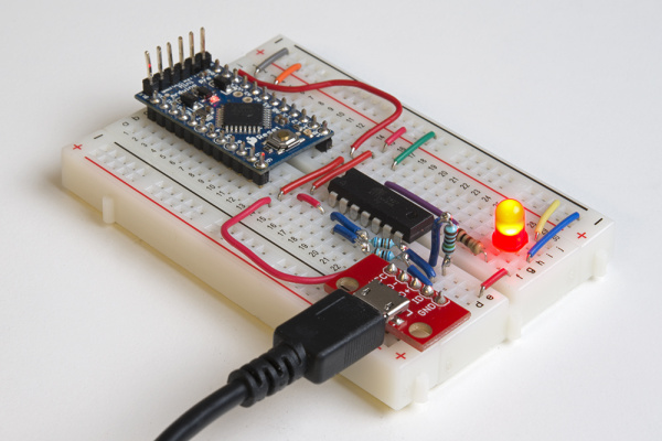
How to Install an ATtiny Bootloader With Virtual USB
Introduction
In this tutorial, we'll show you how to use Arduino to install the micronucleus bootloader, which has V-USB, onto an ATtiny84. These steps will work for other ATtiny chips, but you'll need to change things like the pins_arduino.h file and target parameters in avrdude.
By following this guide, you will be able to upload Arduino sketches directly to the ATtiny84 over USB without needing to use a programming device (such as another Arduino or FTDI chip).
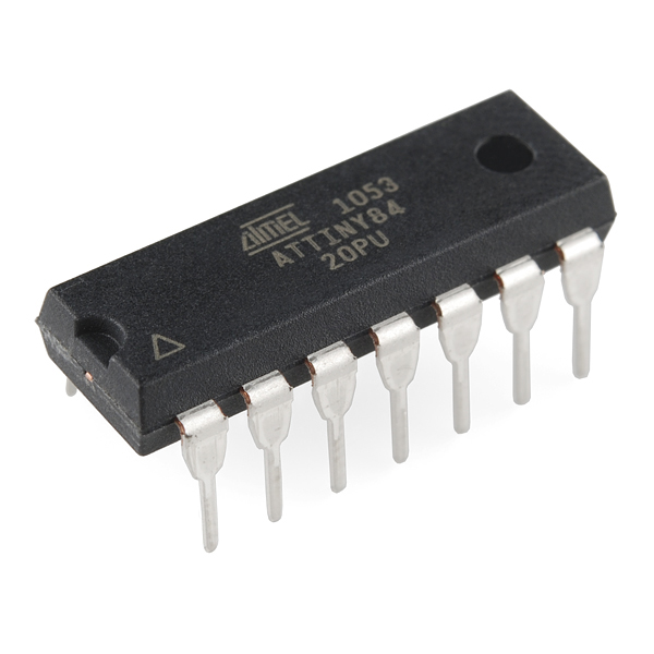
The Atmel AVR ATtiny84 is very similar to the ATtiny85 but with a few more I/O pins (six more, to be exact). If you like working with very small, inexpensive microcontrollers, the ATtiny84 and lower-power ATtiny84A are good options. Either the ATtiny84 or ATtiny84A will work for this tutorial.
AVR 14 Pin 20MHz 8K 12A/D - ATtiny84
COM-11232In this tutorial, we'll show you how to:
- Load Arduino ISP (In-System Programmer) on an Arduino
- Install the micronucleus bootloader on the ATtiny84
- Manually change fuses in the ATtiny84 to allow USB programming
- Create a new board definition in Arduino for the ATtiny84
- Install any necessary USB drivers
- Upload example firmware from Arduino IDE to the ATtiny84
The ATtiny microcontrollers are fantastic little chips but often suffer from low programming space. The ATtiny84 and 85 have 8k of flash memory (compared to 32k in the ATmega328p, the most commonly found microcontroller on Arduino platforms). A bootloader like micronucleus allows us to upload firmware to the microcontroller over a "virtual" USB (V-USB) connection rather than using a separate microcontroller for programming. The downside is that micronucleus uses 2k of the available flash, leaving us with only 6k of flash for our program!
However, using a bootloader potentially reduces the production cost of a custom Arduino board if you don't want to rely on separate hardware for programming.
Parts List
To follow along, you will need these parts:
You Will Also Need
- 2x 68Ω Resistors
- 1x 1.5 kΩ Resistor
Resistors
Suggested Reading
Before moving along, we recommend you have familiarity with the following concepts.
Load Arduino ISP
To get started, we'll need to use another Arduino as an In-System Programmer (ISP) to send firmware to the target device (our ATtiny84). We'll only need to do this once in order to upload the micronucleus bootloader.
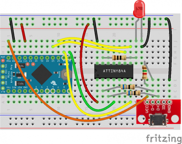
Hardware Connections
To start, make the following connections:
Upload ArduinoISP Sketch
Download the latest Arduino IDE.
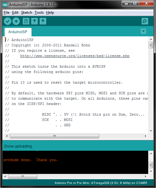
Connect an FTDI breakout to the Arduino Pro Mini. In Arduino, select File > Examples > ArduinoISP > ArduinoISP. Select your Arduino board in Tools:
- Board: Arduino Pro or Pro Mini
- Processor: ATmega328 (3.3V, 8MHz)
- Port: \
Click upload to burn the Arduino ISP firmware to the Arduino Pro Mini.
Install Micronucleus
Micronucleus is a bootloader created for ATtiny microcontrollers. It has V-USB built in so that we can send compiled firmware over a virtual USB connection.
When we say "virtual USB," we're actually mimicking low-speed USB with GPIO pins on the ATtiny, since there is no actual USB hardware on the ATtiny84. Essentially, the V-USB library bit-bangs the differential pair signaling of USB communications to make the USB host on our computer think we're transferring information using the USB protocol.
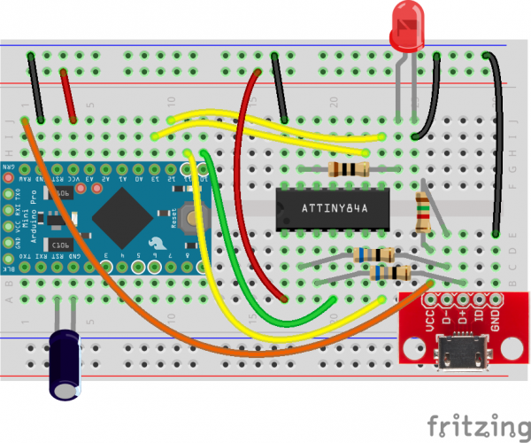
Hardware Setup
Add a 10μF capacitor between the RESET and GND pins of the Arduino. Watch the polarity! The capacitor will prevent the Arduino from entering bootloader mode so that it will pass the compiled firmware to the connected ATtiny rather than trying to program itself.
Upload Micronucleus to the ATtiny84
Head to the micronucleus GitHub repository to clone the bootloader or download the zip here.
Unzip the folder.
The Arduino IDE comes with a tool called AVRDUDE, which is a piece of software that can be used to download and upload firmware, read and write fuses, and manipulate ROM and EEPROM on AVR microcontrollers. Whenever you upload code to an AVR-based Arduino, the Arduino IDE is quietly calling AVRDUDE in the background to make that happen.
We're going to call AVRDUDE manually to send a piece of pre-compiled firmware to the ATtiny.
Open a command terminal and navigate to \
cd \<Arduino Directory\>/hardware/tools/avr/bin
Enter the following command, changing \COM65 on Windows).
avrdude -C ../etc/avrdude.conf -c arduino -p t84 -P <Serial Port> -b 19200 -U flash:w:<micronucleus Directory>/firmware/releases/t84_default.hex
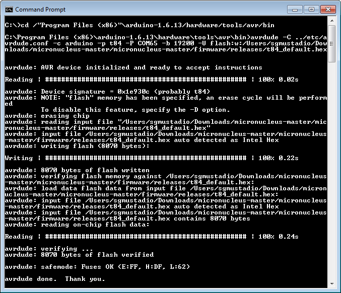
Your output should look similar to the following.
Change Fuses
Most microcontrollers come with a number of configuration bits that reside in nonvolatile memory outside of the normal program space. In AVR chips, like our ATtiny84, these bits are known as "fuses." By default, the fuses on a new ATtiny84 are set to:
- Divide the clock by 8
- Disabled brown-out detection
- No self-programming
We want to change the fuses so that we have:
- No clock divider
- Brown-out detection at 2.7V (not necessary, but useful if running off battery)
- Self-programming
To see which fuses need to be changed, select ATtiny84 from the dropdown list on the AVR Fuse Calculator site.
Burning Fuses with AVRDUDE
If you change the features on the fuse calculator, you'll see that we need to set the following:
- Low Fuse Byte:
0xE2 - High Fuse Byte:
0xDD - Extended Fuse Byte:
0xFE
To do that, we'll use AVRDUDE. Once again, navigate to the directory with AVRDUDE in Arduino and execute the following command:
avrdude -C ../etc/avrdude.conf -c arduino -p t84 -P <Serial Port> -b 19200 -U lfuse:w:0xe2:m -U hfuse:w:0xdd:m -U efuse:w:0xfe:m
Verify that the fuses have been written with the following:
avrdude -C ../etc/avrdude.conf -c arduino -p t84 -P <Serial Port> -b 19200 -U lfuse:r:-:i
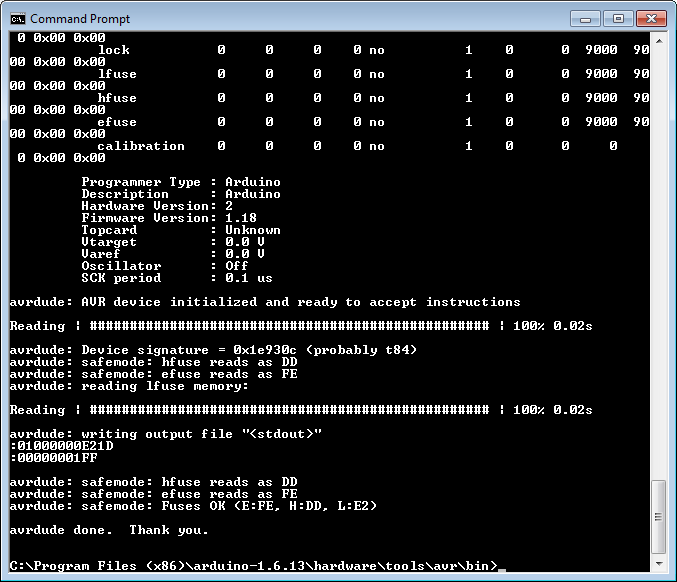
While you are telling AVRDUDE to specifically read the lfuse, it will print out the state of all the fuses. You should see the following at the bottom of the printout:
avrdude: safemode: Fuses OK (E:FE, H:DD, L:E2)
Create an Arduino Board Definition
To be able to program the ATtiny84 from Arduino, we need to make a custom board definition. There are three main parts for a board definition, and we'll create each one:
- boards.txt -- Information about the microcontroller (clock speed, program space, etc.)
- platform.txt -- Extra information the compiler might need and which loader tool to use (e.g., AVRDUDE)
- pins_ardiuno.h -- Tells the compiler which pins in code map to which pins on the microcontroller
Additionally, we'll need to copy over the micronucleus loader tool from the micronucleus project directory to the Arduino directory. The loader tool will be used to send compiled firmware to the ATtiny84 (much as AVRDUDE does).
boards.txt
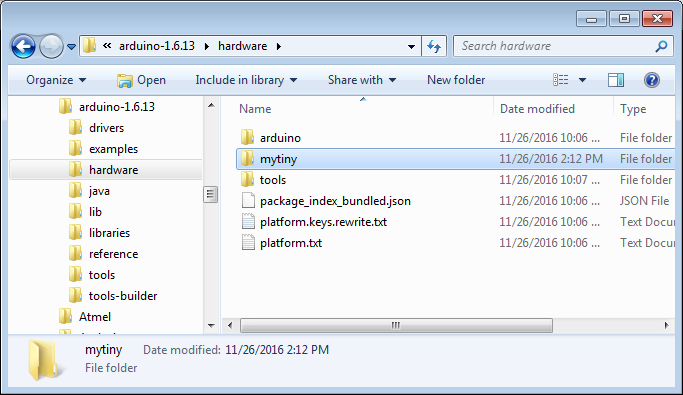
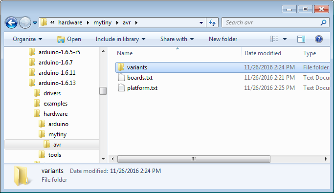
Navigate to \
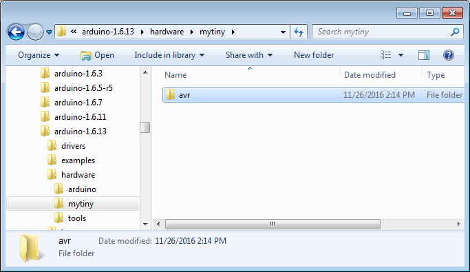
In that directory, create another directory that corresponds to the target microcontroller family, "avr" in this case.
In the avr directory, create a file named boards.txt and copy in the following text:
menu.cpu=Processor

################################################################################

MyTiny.name=MyTiny (ATtiny84, 3.3V, 8Mhz)

MyTiny.upload.using=micronucleusprog
MyTiny.upload.protocol=usb
MyTiny.upload.tool=micronucleus
MyTiny.upload.maximum_size=6012

MyTiny.build.mcu=attiny84
MyTiny.build.f_cpu=8000000L
MyTiny.build.board=MYTINY
MyTiny.build.core=arduino:arduino
MyTiny.build.variant=tiny14
platform.txt
In the avr directory, create a file named platform.txt and copy in the following:
name=MyTiny Boards
version=0.0.1

# Default "compiler.path" is correct, change only if you want to overidde the initial value
compiler.path={runtime.tools.avr-gcc.path}/bin/
compiler.c.cmd=avr-gcc
compiler.c.flags=-c -g -Os -w -ffunction-sections -fdata-sections -MMD
compiler.c.elf.flags=-Os -Wl,--gc-sections
compiler.c.elf.cmd=avr-gcc
compiler.S.flags=-c -g -x assembler-with-cpp
compiler.cpp.cmd=avr-g++
compiler.cpp.flags=-c -g -Os -w -fno-exceptions -ffunction-sections -fdata-sections -MMD
compiler.ar.cmd=avr-ar
compiler.ar.flags=rcs
compiler.objcopy.cmd=avr-objcopy
compiler.objcopy.eep.flags=-O ihex -j .eeprom --set-section-flags=.eeprom=alloc,load --no-change-warnings --change-section-lma .eeprom=0
compiler.elf2hex.flags=-O ihex -R .eeprom
compiler.elf2hex.cmd=avr-objcopy
compiler.ldflags=
compiler.size.cmd=avr-size
# this can be overriden in boards.txt
build.extra_flags=

# AVR compile patterns
# --------------------

## Compile c files
recipe.c.o.pattern="{compiler.path}{compiler.c.cmd}" {compiler.c.flags} -mmcu={build.mcu} -DF_CPU={build.f_cpu} -DARDUINO={runtime.ide.version} -DARDUINO_{build.board} -DARDUINO_ARCH_{build.arch} {build.extra_flags} {includes} "{source_file}" -o "{object_file}"

## Compile c++ files
recipe.cpp.o.pattern="{compiler.path}{compiler.cpp.cmd}" {compiler.cpp.flags} -mmcu={build.mcu} -DF_CPU={build.f_cpu} -DARDUINO={runtime.ide.version} -DARDUINO_{build.board} -DARDUINO_ARCH_{build.arch} {build.extra_flags} {includes} "{source_file}" -o "{object_file}"

## Compile S files
recipe.S.o.pattern="{compiler.path}{compiler.c.cmd}" {compiler.S.flags} -mmcu={build.mcu} -DF_CPU={build.f_cpu} -DARDUINO={runtime.ide.version} -DARDUINO_{build.board} -DARDUINO_ARCH_{build.arch} {build.extra_flags} {includes} "{source_file}" -o "{object_file}"

## Create archives
recipe.ar.pattern="{compiler.path}{compiler.ar.cmd}" {compiler.ar.flags} "{archive_file_path}" "{object_file}"

## Combine gc-sections, archives, and objects
recipe.c.combine.pattern="{compiler.path}{compiler.c.elf.cmd}" {compiler.c.elf.flags} -mmcu={build.mcu} -o "{build.path}/{build.project_name}.elf" {object_files} "{archive_file_path}" "-L{build.path}" -lm

## Create eeprom
recipe.objcopy.eep.pattern="{compiler.path}{compiler.objcopy.cmd}" {compiler.objcopy.eep.flags} "{build.path}/{build.project_name}.elf" "{build.path}/{build.project_name}.eep"

## Create hex
recipe.objcopy.hex.pattern="{compiler.path}{compiler.elf2hex.cmd}" {compiler.elf2hex.flags} "{build.path}/{build.project_name}.elf" "{build.path}/{build.project_name}.hex"

## Compute size
recipe.size.pattern="{compiler.path}{compiler.size.cmd}" -A "{build.path}/{build.project_name}.elf"
recipe.size.regex=^(?:\.text|\.data|\.bootloader)\s+([0-9]+).*
recipe.size.regex.data=^(?:\.data|\.bss|\.noinit)\s+([0-9]+).*
recipe.size.regex.eeprom=^(?:\.eeprom)\s+([0-9]+).*


# Micronucleus Loader
# -------------------
tools.micronucleus.cmd.path={runtime.hardware.path}/../tools
tools.micronucleus.upload.params.verbose=-verbose
tools.micronucleus.upload.params.quiet=
tools.micronucleus.upload.pattern="{cmd.path}/micronucleus" --timeout 60 "{build.path}/{build.project_name}.hex"
#tools.micronucleus.upload.pattern="{cmd.path}/micronucleus" --run --timeout 60 "{build.path}/{build.project_name}.hex"
#tools.micronucleus.upload.pattern="{cmd.path}" -cdigispark --timeout 60 -Uflash:w:{build.path}/{build.project_name}.hex:i

# USB Default Flags
# Default blank usb manufacturer will be filled it at compile time
# - from numeric vendor ID, set to Unknown otherwise
build.usb_manufacturer=
build.usb_flags=
Pin Definitions
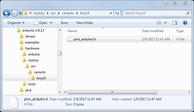
At this point, we need to create a custom pin definitions file. Create a directory in avr with the name variants:
Create another directory in variants named tiny14. In tiny14, create a file named pins_arduino.h.
Copy the following code into pins_arduino.h. Note that the original contents of this file come from the ATtiny cores for Arduino project.
language:c
/*
  pins_arduino.c - pin definitions for the Arduino board
  Part of Arduino / Wiring Lite

  Copyright (c) 2005 David A. Mellis

  This library is free software; you can redistribute it and/or
  modify it under the terms of the GNU Lesser General Public
  License as published by the Free Software Foundation; either
  version 2.1 of the License, or (at your option) any later version.

  This library is distributed in the hope that it will be useful,
  but WITHOUT ANY WARRANTY; without even the implied warranty of
  MERCHANTABILITY or FITNESS FOR A PARTICULAR PURPOSE.  See the GNU
  Lesser General Public License for more details.

  You should have received a copy of the GNU Lesser General
  Public License along with this library; if not, write to the
  Free Software Foundation, Inc., 59 Temple Place, Suite 330,
  Boston, MA  02111-1307  USA

  $Id: pins_arduino.c 565 2009-03-25 10:50:00Z dmellis $

  Modified 28-08-2009 for attiny84 R.Wiersma
  Modified 09-10-2009 for attiny45 A.Saporetti
*/

#ifndef Pins_Arduino_h
#define Pins_Arduino_h

#include <avr/pgmspace.h>

// ATMEL ATTINY84 / ARDUINO
//
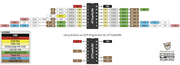
//                           +-\/-+
//                     VCC  1|    |14  GND
//             (D 10)  PB0  2|    |13  AREF (D  0)
//             (D  9)  PB1  3|    |12  PA1  (D  1)
//                     PB3  4|    |11  PA2  (D  2)
//  PWM  INT0  (D  8)  PB2  5|    |10  PA3  (D  3)
//  PWM        (D  7)  PA7  6|    |9   PA4  (D  4)
//  PWM        (D  6)  PA6  7|    |8   PA5  (D  5)        PWM
//                           +----+

const static uint8_t A0 = 0;
const static uint8_t A1 = 1;
const static uint8_t A2 = 2;
const static uint8_t A3 = 3;
const static uint8_t A4 = 4;
const static uint8_t A5 = 5;
const static uint8_t A6 = 6;
const static uint8_t A7 = 7;

#define digitalPinToPCICR(p)    ( ((p) >= 0 && (p) <= 10) ? (&GIMSK) : ((uint8_t *)0) )
#define digitalPinToPCICRbit(p) ( ((p) <= 7) ? PCIE0 : PCIE1 )
#define digitalPinToPCMSK(p)    ( ((p) <= 7) ? (&PCMSK0) : (((p) <= 10) ? (&PCMSK1) : ((uint8_t *)0)) )
#define digitalPinToPCMSKbit(p) ( ((p) <= 7) ? (p) : (10 - (p)) )

#ifdef ARDUINO_MAIN

// these arrays map port names (e.g. port B) to the
// appropriate addresses for various functions (e.g. reading
// and writing)
const uint16_t PROGMEM port_to_mode_PGM[] =
{
  NOT_A_PORT,
  (uint16_t)&DDRA,
  (uint16_t)&DDRB,
};

const uint16_t PROGMEM port_to_output_PGM[] =
{
  NOT_A_PORT,
  (uint16_t)&PORTA,
  (uint16_t)&PORTB,
};

const uint16_t PROGMEM port_to_input_PGM[] =
{
  NOT_A_PORT,
  (uint16_t)&PINA,
  (uint16_t)&PINB,
};

const uint8_t PROGMEM digital_pin_to_port_PGM[] =
{
  PA, /* 0 */
  PA,
  PA,
  PA,
  PA,
  PA,
  PA,
  PA,
  PB, /* 8 */
  PB,
  PB,
};

const uint8_t PROGMEM digital_pin_to_bit_mask_PGM[] =
{
  _BV(0), /* port A */
  _BV(1),
  _BV(2),
  _BV(3),
  _BV(4),
  _BV(5),
  _BV(6),
  _BV(7),
  _BV(2), /* port B */
  _BV(1),
  _BV(0),
};

const uint8_t PROGMEM digital_pin_to_timer_PGM[] =
{
  NOT_ON_TIMER,
  NOT_ON_TIMER,
  NOT_ON_TIMER,
  NOT_ON_TIMER,
  NOT_ON_TIMER,
  TIMER1B, /* OC1B */
  TIMER1A, /* OC1A */
  TIMER0B, /* OC0B */
  TIMER0A, /* OC0A */
  NOT_ON_TIMER,
  NOT_ON_TIMER,
};

#endif

#endif
If you look through the platform.txt file, you'll see that the loader tool is micronucleus and not avrdude. Because Arduino does not come with the micronucleus loader tool, we need to build it or copy it from the micronucleus project directory.
Build the Micronucleus Loader (Mac)
First, you'll need to make sure you have Homebrew installed. Then, open a command terminal and enter:
cd <micronucleus Directory>/commandline
brew install libusb-compat
make
Navigate to \
Build the Micronucleus Loader (Linux)
Navigate to the micronucleus project directory and make the loader:
cd <micronucleus Directory>/commandline
sudo apt-get install libusb-dev
make
Navigate to \
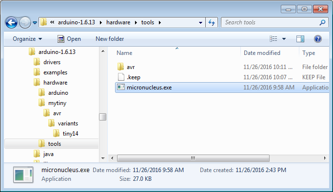
Copy the Micronucleus Executable (Windows)
Navigate to \
Install USB Drivers
Because micronucleus requires custom drivers based on libusb, many operating systems will need to have the custom drivers installed or perform some custom configuration. Find your operating system below and follow the instructions.
Windows
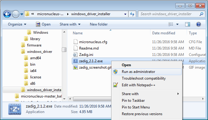
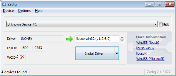
Unfortunately, Windows doesn't know what to do with the micronucleus bootloader on the ATtiny84. It comes up as an Unknown USB Device, so we'll fix that with a custom driver. Lucky for us, the micronucleus project already comes with one.
Plug in a USB micro cable from your computer to the USB micro breakout on the breadboard. Windows will likely tell you that no driver could be found.
Navigate to \
In the interface, select Unknown Device #1 from the dropdown menu, and make sure that libusb-win32 is selected for the driver.
Click Install Driver and let Zadig do its thing. Close out of Zadig once the installation is complete.
Mac
If you installed libusb from the previous section, you should be all set.
Linux
You have two choices. You can either run Arduino with root privileges in order to send data to an "unknown" USB device, or you can install a set of udev rules to allow regular users to upload programs. To install the udev rules, run the following commands:
cd \<micronucleus Directory>/commandline
sudo cp 49-micronucleus.rules /etc/udev/rules.d/
Example: Blinky
We should have everything set up to flash a program onto the ATtiny84 from the Arduino IDE! But first, let's simplify the hardware.
Hardware Setup
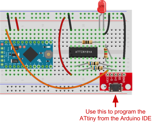
We can modify our hardware to disconnect the programming lines from the Arduino Pro Mini, which will free up some GPIO on the ATtiny. We'll still want to use the Pro Mini's voltage regulator to drop the USB voltage from 5V to 3.3V.
The Code
Close and reopen the Arduino IDE to load the new board definition files.
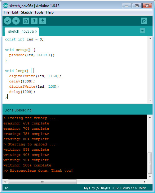
In a new sketch, copy in the following:
language:c
const int led = 0;

void setup() {
  pinMode(led, OUTPUT);
}

void loop() {
  digitalWrite(led, HIGH);
  delay(1000);
  digitalWrite(led, LOW);
  delay(1000);
}
Upload and Run
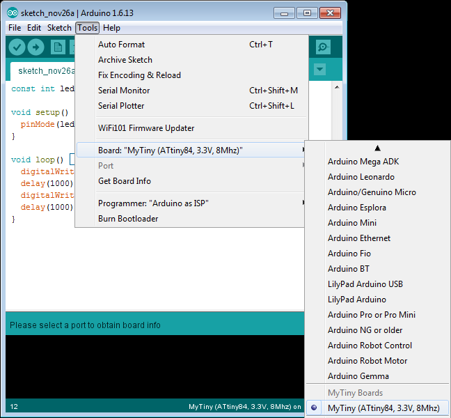
In Tools > Board, you should see only one option under MyTiny Boards. Select it.
- Unplug USB cable
- Press Upload in the Arduino IDE
- Wait for the phrase "Uploading..." to appear just above the Arduino console
- Plug in the USB cable
- Wait five seconds for the ATtiny84 to reboot and time out of the bootloader to start running our Blinky sketch
And that's it! You should see the LED begin to blink on and off.
Resources and Going Further
While this is a lot of information to take in, it shows how to hack the Arduino IDE to load custom board definitions. These steps should work for other ATtiny devices that are supported by the micronucleus project, such as:
You might have to modify the pins_arduino.h file, however, if you plan to use a different ATtiny.
ATtiny84 Pinout
If you need additional support, please check out the following resources.
If you want to go further with the ATtiny, please check out our additional tutorials that showcase the ATtiny:
