Wake-on-Shake Hookup Guide
 Toni_K,
  SFUptownMaker
Introduction
The SparkFun Wake-on-Shake is a wonderful little sensor board that gives you the ability to put your project into hibernation until bumped or shaken awake. This means you can design projects meant to stay inert for long periods of time, possibly even several years, depending on the battery type used to power the project.
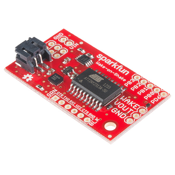
SparkFun Wake on Shake
SEN-11447Materials Required
We recommend the following materials in order to follow along with this tutorial.
Suggested Reading
If you aren't familiar with the following concepts, we recommend you read over these tutorials before continuing on to work with the Wake-on-Shake.
Hardware Overview
Basic Operation
The Wake-on-Shake has a rather simple concept of operation. Once a power supply is connected, as well as a load circuit, the Wake-on-Shake will wake up upon being bumped, touched, or moved, power up the load circuit for 5 seconds, and then return to an inert state.
The sensitivity of bumps or movement can be changed over the serial connection. The user also has the option to increase or decrease the delay time for powering the load circuit.
Power Connections
The Wake-on-Shake has a very low power consumption of <2uA at 3.7V. However, the board itself can be powered with 2.0-5V. There are two different options available for powering the Wake-on-Shake.
- JST Connector - The JST connector on-board is designed to interface with any single cell lipo batteries available from SparkFun. These will power your Wake-on-Shake at 3.7V.
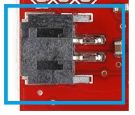
Alternatively, you can also use the JST Jumper Wire Assembly to connect your project to a power source.
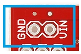
- Power Input Headers - The second option for powering your Wake-on-Shake is through the VIN/GND pins broken out on the top of the board. You will need to solder either bare wires or headers to these pins in order to hook up a power supply to your board through these.
ICSP Header
The ISP header on-board follows the standard 6-pin AVR programming header. This gives the user access to reprogram the ATTiny2313A. However, the Wake-on-Shake can be used to its full potential without reprogramming. This is an advanced feature.
Keep in mind that there is no bootloader on this device. You can use any standard 6-pin AVR programmer to upload code via this header. Depending on the type of programmer you are using, you may need to solder either male or female headers onto these pins.
Serial Connection Header
The serial connection header has the standard mating footprint for any 3.3V FTDI Breakout board or FTDI USB-to-Serial cable. For our example, we will be using the breakout board. You can use other materials for serial communication with the Wake-on-Shake, but keep in mind that they should run at 3.3V logic levels.
This header also allows you to access the ADXL362 onboard directly, as well as the EEPROM storage for the ATTIny2313A.
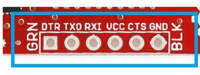
While it is possible to connect the load to the serial port for power, it is possible to draw too much current through these pins. That can lead to damage to the ATTiny2313A, and should be avoided if possible.
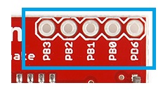
General I/O Pins
The general I/O pins broken out on the Wake-on-Shake can be read for information on their statuses, by default. Serial commands exist to read and write the status of these pins.
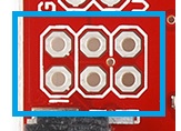
Load Connection Pins
The load connection pins are the main connection point for the rest of your project.
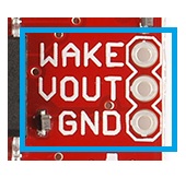
WAKE - The WAKE pin determines the functionality of the pass transistor on the Wake-on-Shake. When held above ~2.7V, the transistor will remain on until released. This allows the load to gate its own power for as long as needed. In other words, this gives the load the power to control when its power is disconnected.
VOUT - This is power output for the rest of your circuit. Output is dependent on the supply input for the Wake-on-Shake.
GND - The name says it all! This is your ground connection for your load circuit.
Onboard ICs
- ATTiny2313A
The microcontroller driving the Wake-on-Shake is the ATTiny2313A. This is a small 20-pin IC with low-power consumption. Even in active mode, this IC only pulls 190uA, and draws as little as 24uA in idle mode.
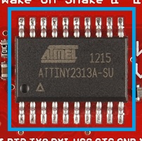
This IC holds the main code driving the Wake-on-Shake, and can be reprogrammed over the serial connection header.
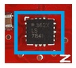
- ADXL362
The accelerometer onboard that watches for bumps, knocks, or other movement triggers for the Wake-on-Shake is the ADXL362. The 3-axis accelerometer can measure 2g, 4g or 8g ranges. It has a high resolution of 1 mg/LSB at +/- 2g, and interfaces over an SPI connection.
This accelerometer draws very little power, only 3uA at 400Hz, 270 nA when in motion-triggered wake-up mode, and down to 10nA in standby mode.
Command Set
If you would like to simply test out the Wake-on-Shake over a serial connection before permanently embedding it in your project, take a look at the following command settings. These will also allow you to customize your hardware settings depending on your particular project applications. If you need a little refresher on how to connect the Wake-on-Shake with a serial terminal, check out our tutorial on Serial Terminal Basics!
Make sure you've connected an external power supply to the JST connector or the 0.1" headers next to it!
Communication Settings
Using the serial header interface, the user can communicate with the Wake-on-Shake over a basic terminal connection. You can test out the following commands this way, to determine what is the best functionality of the Wake-on-Shake for your particular application.
For interfacing with the Wake-on-Shake, you will need to use the following serial terminal settings:
- Baud Rate: 9600 bps
- Data Size: 8 bits
- Parity: none
- Stop Bits: 1
- Voltage Level: 3.3V
Standard Commands
Threshold Level
t<0-248><cr>|<lf>: This command will set the threshold level at which the device will wake from sleep. Default value from the factory is 150mG. This setting will accept any value between 0 and 2,048.Delay
d<2000-65535><cr>|<lf>: This command sets the delay between the device waking up and returning to sleep. The default value is 5s. The input number is in milliseconds, and can range from 2,000 to 65,535.Sleep
z: This command will set the device to sleep. Functionally, this "shortcuts" the delay command, moving the sleep timer closer to zero. This allows the Wake-on-Shake to finish any general bookkeeping commands before powering down. After receiving this command, sleep mode will occur within 35ms.
Advanced User Commands
Pin State
p<0-3|6>: Print the current state of the defined pin on the 0.1" header on the board. Number input by user defines pin (i.e.,p0prints PB0 pin state). Pin state can either be '0' or '1'.Drive Pin Low
L<0-3|6>: Drive user-defined pin low.Drive Pin High
H<0-3|6>: Drive user-defined pin high.Buffer Write
b<0-255><cr>|<lf>: Place an 8-bit value into the device's write buffer. This value can been written to either an arbitrary EEPROM address -or- to an arbitrary register in the ADXL362, depending on the next command.Write Buffer to ADXL362
w<0-64><cr>|<lf>: Write the 'Buffer Write' value into the register of the ADXL362 specified in this command. Please refer to the ADXL362 datasheet for information about the registers.Write Buffer to EEPROM
e<0-127><cr>|<lf>: Write the 'Buffer Write' value nto the ATTiny2313A EEPROM memory at the address specified in this command. This can be used to store data in non-volatile memory by the user's application, or to alter operation settings not normally exposed to the user.Print ADXL362 Register
r<0-64><cr>|<lf>: Print the contents of the sepcified ADXL362 register to the serial port.Print ATTiny2313A EEPROM address
E<0-127><cr>|<lf>: Print the contents of the specified ATTIny2313A EEPROM address to the serial port.
EEPROM Memory Space Reference
Thanks to the on-board EEPROM memory storage, configuration paramters are saved even if power is removed from the Wake-on-Shake. These values can be changed via the serial interface. There are five settings stored in the EEPROM of which the user should be aware.
| Addr | Name | Default | Description |
|---|---|---|---|
| 0-1 | ATHRESH | 150 | Activity threshold setting (0-2048) |
| 2-3 | WAKE_OFF S | 5000 | Time after wake-up before returning to sleep mode(0-655535) |
| 4-5 | ITHRESH | 50 | Inactivity threshold setting (0-2048) |
| 6-7 | ITIME | 15 | # samples (12.5Hz) below ITHRESH before wake interrupt enabled |
| 127 | KEY_ADDR | 123 | If !=123, restore EEPROM locations to default |
- Key Address is used to record whether EEPROM values have been configured or not. On the first power up, the firmware will check to see if that location is set to a specific value (123). If not, it will initialize the other memory locations, along with the key address itself.
Inactivity Threshold is the level below which the ADXL362 must sense movement before it resets and begins waiting for motion again. By default, this is 50mg.
Inactivity Time Delay is the amount of time the motion threshold should be below the inactivity threshold before the reset to the motion trigger occurs. Be default, this value is 15. This translates to about 2.5 seconds.
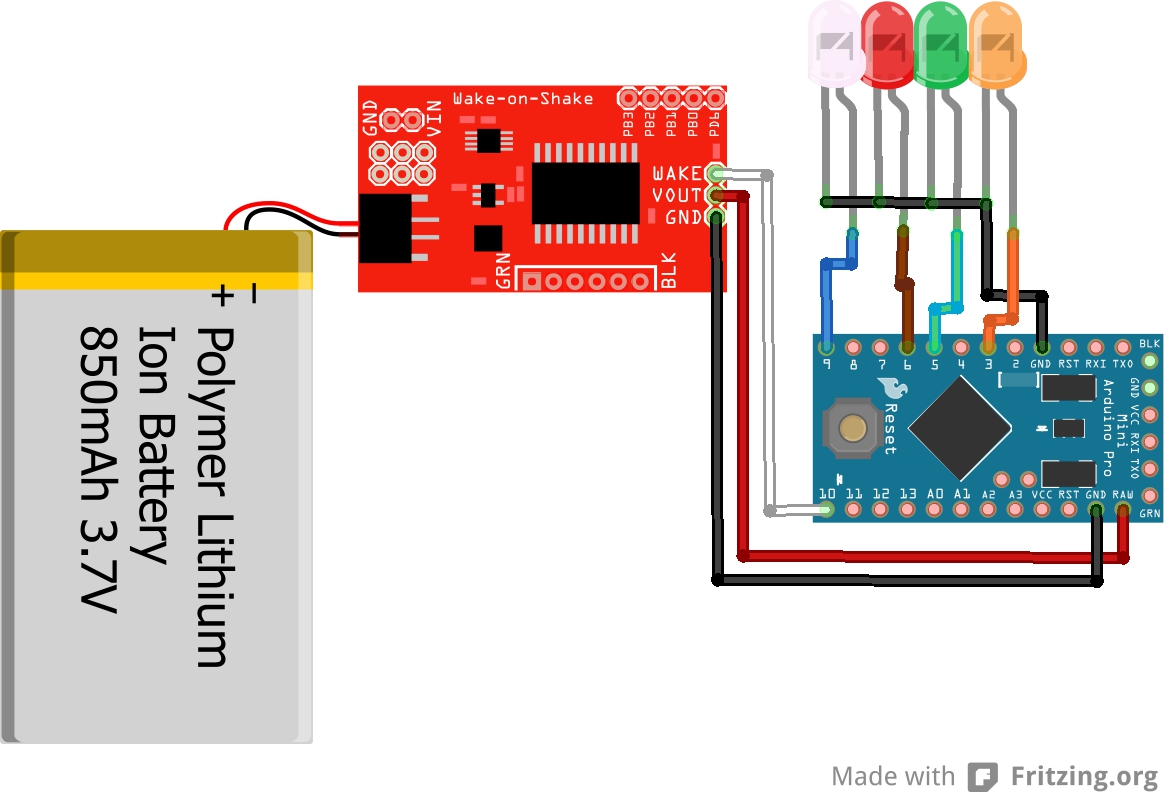
Hardware Hookup
In this hardware example, we'll show you how to use the Wake-on-Shake to power up some LEDs momentarily. The LEDs could be behind a painting, on a holiday prop, or used as an indicator if something was bumped or moved.
You will need to either solder wires directly between your boards and LEDs, or solder on headers and use jumper wires between all the components. If you are unsure how to do this, please check our tutorial on soldering here.
Connect LEDs to Arduino
Take four of the LEDs, and connect them to your Arduino. For our example, we use different colored LEDs to make the hookup guide clear, but feel free to use the same color LEDs if you'd prefer.
You will want to connect the anode leg (the longer leg) of each LED to one of the digital pins. For our example, we need to use PWM capable pins.
The connections are as follows:
Anode legs of LEDs → Pro Mini
- LED1 → D3
- LED2 → D5
- LED3 → D6
- LED4 → D9
Once all the anodes are connected, you will want to connect all the cathode legs of the LEDs to ground.
Connect Wake-on-Shake to Arduino
It's now time to connect the Pro Mini to the Wake-on-Shake. There are only three pins that need to be connected between the two boards.
The connections are as follows:
Pro Mini → Wake-on-Shake
- D10 → WAKE
- RAW → VOUT
- GND → GND
D10 will drive the WAKE pin, controlling the behavior of the Wake-on-Shake. VOUT and GND need to be connected to the Arduino in order to power both the Pro-Mini and the LEDs connected to the microcontroller.
Remember that the Wake-on-Shake passes through the unregulated power from the LiPo battery, thus we attach it to the RAW pin on the Arduino to make sure the voltage from the battery gets regulated by the voltage regulator on the Pro Mini.
Power the Project
Now that everything is hooked up together, it's time to power your project. Plug the JST connector of the LiPo battery into the JST connector on the Wake-on-Shake. Your project should power on immediately, as there is no On/Off switch.
Final Circuit
Once you have everything hooked up together, your circuit should look something like the following.
Code
Now that you have everything hooked up, it's time to program your Arduino Pro Mini and get your project running!
Upload the Code
Download the zip of the demo sketch from the link below, or find the most up-to-date code in the GitHub repository.
Upload this sketch to your Arduino. If you are unsure how to do this, please review our tutorial on using the 3.3V Pro Mini here.
Code Functionality
In the first section of the code, we must define the pin numbers on the Arduino that are connected to either the LEDs or the Wake-on-Shake.
language:c
//Define LED Pin Connections
int LED1 = 3;
int LED2 = 5;
int LED3 = 6;
int LED4 = 9;

//Define Wake-on-Shake WAKE pin connection
int WAKE = 10;
The setup loop of the sketch is where the main action occurs. Remember, we will only be running a few basic functions when the system turns on.
We first define the connected pins as outputs, as the Arduino will be driving all of these pins. We then write the WAKE pin HIGH, to prevent the Wake-on-Shake from returning to the 'sleep' state. This allows us to run through the desired functionality on the Arduino, before returning to the low-power state.
We then slowly brighten each LED using the analogWrite function. Once the LED has reached full brightness, the Pro Mini turns it off and turns the next LED on.
Once all the LEDs have been cycled through, we pull the WAKE pin LOW, allowing the Wake-on-Shake to enter low-power mode and put the system to sleep.
language:c
void setup() {

  //Set LED pin connections as outputs
  pinMode(LED1, OUTPUT);
  pinMode(LED2, OUTPUT);
  pinMode(LED3, OUTPUT);
  pinMode(LED4, OUTPUT);
  pinMode(WAKE, OUTPUT);

  //Set WAKE pin HIGH to prevent the Wake-on-Shake from 'sleeping'
  digitalWrite(WAKE, HIGH);

  //Functions to occur on each wake-up of the system
  //This will fade the LEDs up to full brightness one by one

  //Slowly birghten the first LED
  for( int i = 0; i<255; i++)
  {
    analogWrite(LED1, i);
    delay(20);
  }
  //Turn off the LED
  digitalWrite(LED1, LOW);

  for( int i = 0; i<255; i++)
  {
    analogWrite(LED2, i);
    delay(20);
  }
  digitalWrite(LED2, LOW);

  for( int i = 0; i<255; i++)
  {
    analogWrite(LED3, i);
    delay(20);
  }
  digitalWrite(LED3, LOW);

  for( int i = 0; i<255; i++)
  {
    analogWrite(LED4, i);
    delay(20);
  }
  digitalWrite(LED4, LOW);

  //Allow the Wake-on-Shake to go to sleep
  digitalWrite(WAKE, LOW);
}
In the final section of the code, we have the main loop. Again, there are no functions occurring in here, as the Arduino will not be remaining on for any extended periods of time.
language:c
    /*********************Main Loop************************/
void loop() {
//No main function here as the Wake-on-Shake will return to low-power mode
}
Example Projects
The Wake-on-Shake can allow you to interact with everyday objects in ways you may have never imagined. To show off it's versatility, here are a few example projects to give you some ideas. E-textiles expert Dia and I each did a fun project using the Wake on Shake. Here's a short video showing what we created:
Dia's project uses the Wake on Shake with a LilyTwinkle and four LEDs to make a twinkling night sky that activates when it's touched. Because of the low power consumption of the Wake on Shake, the painting can hang on the wall for months before needing to be recharged. We've tweaked the sensitivity to a point where all it takes is a gentle touch to activate it; we had it turned up higher, but found that when the level was low enough for a bump on the wall to set it off, the vibrations from the HVAC system turning on and off were keeping the lights on too much of the time, killing the battery!
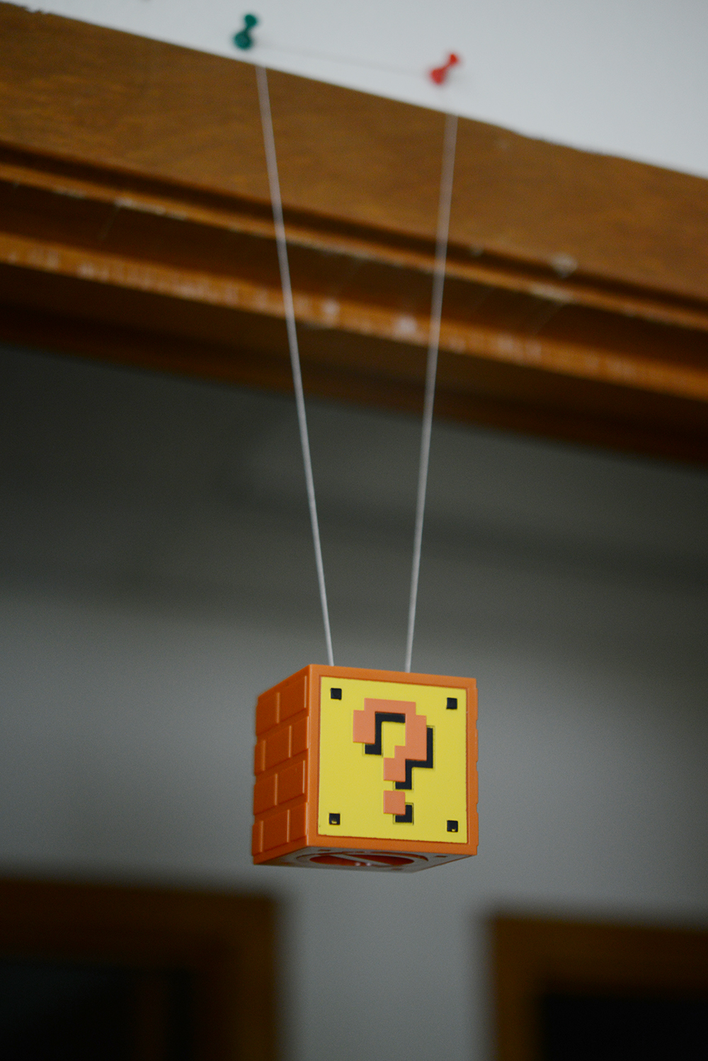
My project uses a toy bank I got at a small Minneapolis kitsch store a few years back. It’s shaped like the iconic "?" block from the original Super Mario Bros. game that shipped with the original NES back in '85. Using the Wake on Shake with its default settings, an Arduino Pro Mini, and our small Audio Breakout Board, I taught my Mario block to give me a satisfying "ka-CHING" whenever I (or anyone else) bump it on the way into my office (it’s hanging in my doorway). I stuffed a little 850mA rechargeable LiPo battery into it, and that kept it running for over five months!
SFE Engineer, Joel, also created a painting project that revolves around the Wake-on-Shake. Some plain white LEDs and some addressable WS2812 LEDs are connected to an Arduino Pro Mini 3.3V, using the Wake-onShake to power it all. The painting sits idle until it is tapped, then it displays a brief yet lovely LED sunset and goes back to sleep. Using a 2000mAh battery, the circuit hasn't needed to be charged in over a year!
What kinds of input would you like to be able to use to activate your products? What can you build with a board that can sit dormant for months without needing to be charged?
Resources and Going Further
Now that you've successfully got your Wake-on-Shake up and running, it's time to incorporate it into your own project!
For more information, check out the resources below:
- Schematic (PDF)
- Eagle Files (ZIP)
- Wake-on-Shake GitHub repository
- SparkFun Product Showcase: Wake on Shake
- SparkFun ElectriCute - Wake on Shake
- ADXL362 Datasheet (PDF)
- ATTiny2313A Datasheet (PDF)
Now that you've successfully got your Wake on Shake up and running, it's time to incorporate it into your own project! You can try adding functions into the main loop of your Arduino code and modify the settings on the Wake-on-Shake to remain fully powered for different amounts of time. Alternatively, you can also try other example code we have posted in the repository.
For an added challenge, try incorporating one of our LiPo Charging boards into your project to charge the battery once it finally does get too low. Or you could use AA batteries or a 9V battery instead of a LiPo battery.
Check out the following resource for more information or inspiration for your own projects!
The Uncertain 7-Cube
If you have any feedback or questions, please visit the comments below or contact our technical support team at TechSupport@sparkfun.com.