Haptic Motor Driver Hook-Up Guide
Contributors:
 LightningHawk
PWM & Analog Input Mode Example: Light Vibes
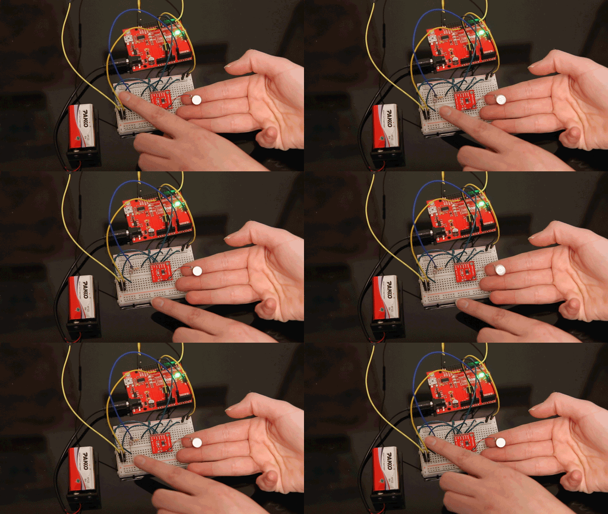
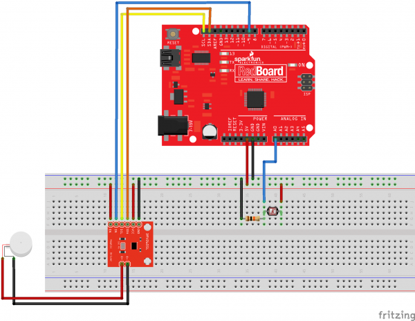
In this example project, we are going to control an ERM motor based on analog input from a photocell that gets mapped to a range from 0-255 and uses that result to set the pulse width modulation of an output pin connected to the IN/TRIG pin on the Haptic Motor Driver. This project will give haptic effects based on the amount of ambient light in an area.
Waving your hand over the photoresistor turns off the motor, and, when you move your hand away, you can feel the ramping effects as the PWM signal increases with the amount of light detected.
Parts Needed
In addition to the basics like hook-up wire, you'll also need the following parts:
The Circuit
Arduino Sketch
language:c
// Control the vibration of an ERM motor
// using PWM and a photoresistor.

#include <Sparkfun_DRV2605L.h>
#include <Wire.h>

SFE_HMD_DRV2605L HMD;
const int analogInPin = A0;  // Analog input pin that the sensor is attached to
const int analogOutPin = 9; // Analog output pin that the Haptic Motor Driver is attached to

int sensorValue = 0;        // value read from the sensor
int outputValue = 0;        // value output to the PWM (analog out)


void setup()
{
  HMD.begin();
  Serial.begin(9600);
  HMD.Mode(0x03); //PWM INPUT
  HMD.MotorSelect(0x0A);
  HMD.Library(7); //change to 6 for LRA motors

}
void loop()
{

 // read the analog in value:
  sensorValue = analogRead(analogInPin);
  // map it to the range of the analog out:
  outputValue = map(sensorValue, 0, 1023, 0, 255);
  // change the analog out value:
  analogWrite(analogOutPin, outputValue);

  // print the results to the serial monitor:
  Serial.print("sensor = ");
  Serial.print(sensorValue);
  Serial.print("\t output = ");
  Serial.println(outputValue);

  // wait 2 milliseconds before the next loop
  // for the analog-to-digital converter to settle
  // after the last reading:
  delay(2);
 }
