Haptic Motor Driver Hook-Up Guide
Contributors:
 LightningHawk
LightningHawk 
Hardware Overview
Parametrics
| Parameter | Description |
|---|---|
| Min-Max Source Voltage | 2V - 5.2V. |
| Special Features | Integrated Haptic Effects & Smart Loop Architecture. |
| Input Signal | PWM, Analog, I2C. |
| Maximum Output Voltage | 10.4V. |
| Haptic Actuator Type | ERM & LRA type motors only. |
| Shut Down Current | 4uA. |
| Quiescent Current | 0.5mA - Important for your battery powered projects. |
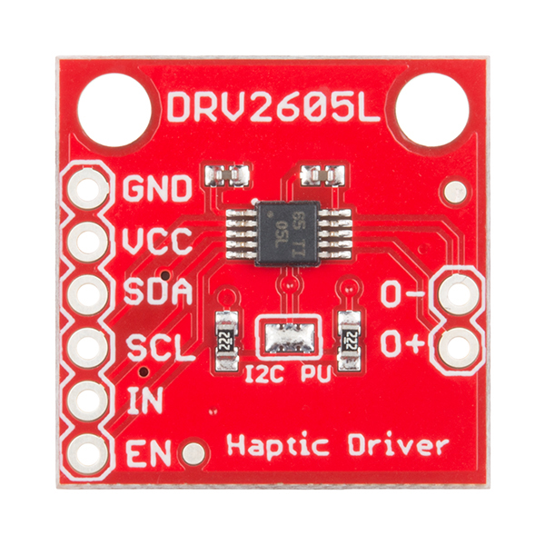
Pin Descriptions
The SparkFun Haptic Motor Driver - DRV2605L breakout board provides 6 pins to provide power to the sensor and I2C bus.
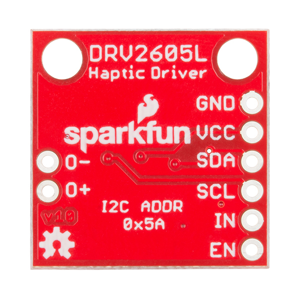
| Pin Label | Description |
|---|---|
| GND | Connect to ground. |
| VCC | Used to power the DRV2605L Haptic Motor Driver. Must be between 2.0 - 5.2V |
| SDA | I2C data |
| SCL | I2C clock |
| IN | Analog and PWM signal input |
| EN | Enable pin. Connect to VCC for most applications. |
| O- | Negative motor terminal. |
| O+ | Positive motor terminal. |
Setting the Jumpers
On the front of the breakout board is a solder jumper:
- I2C PU -- This is a 3-way solder jumper that is used to connect and disconnect the I2C pullup resistors. By default, this jumper is closed, which means that both SDA and SCL lines have connected pullup resistors on the breakout board. Use some solder wick to open the jumper if you do not need the pullup resistors (e.g. you have pullup resistors that are located on the I2C bus somewhere else).