Hackers in Residence - Hacking MindWave Mobile
Introduction
Have you ever wanted to control something just by thinking about it? Well, you're in luck. The MindWave allows you to turn electronic signals that flow in your body into digital signals that can be understood by a microcontroller. There is also the MindWave Mobile, which is designed to interface with your mobile devices.
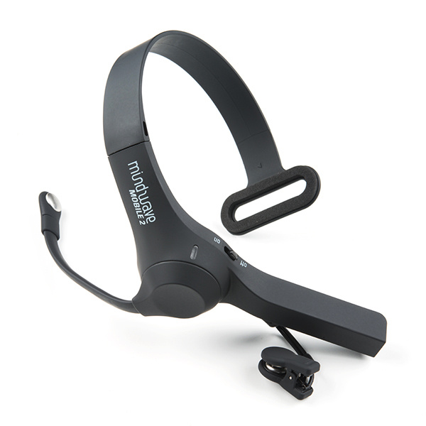
NeuroSky MindWave Mobile 2
SEN-14758This tutorial will serve as half teardown/review and half project. After we explore the inner-workings of the MindWave Mobile, we'll switch gears and focus on hacking it.

Covered in This Tutorial
This tutorial will go over:
- What is MindWave Mobile?
- Configuring the RN42 Bluetooth module
- Pairing MindWave Mobile with the RN42
- What is the data you will see coming out of the MindWave? What does it mean?
- Programming the Arduino with provided source code to see MindWave data
- Using Processing to graph specific values from the digital data
- Next steps, after the MindWave
Suggested Reading
This tutorial builds on some previously covered topics. Please visit any of the links below if you are unfamiliar with the concepts mentioned.
Serial Communication
What is an Arduino?
What is Electricity?
Connecting Arduino to Processing
Serial Terminal Basics
Bluetooth Basics
Using the BlueSMiRF
Suggested Viewing
What is the MindWave Mobile?
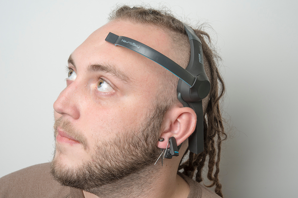
To understand the MindWave and MindWave Mobile, we must first understand what an EEG sensor is. The first recording of the human brain's electric field was made by Hans Berger, a German psychiatrist, in 1924. Berger gave the recording the name electroencephalogram (EEG). Put simply, the EEG is performed by placing electrodes all over the subject's scalp, and then reading in the electrical signals for analysis. Fast forward to today, and you have all of this technology packed into a compact form factor that is the MindWave and the MindWave Mobile.
Project Scope
The amplitude of the EEG is ~ 100 µV when measured on the scalp, and about 1-2 mV when measured on the surface of the brain. The bandwidth of this signal is from under 1 Hz to about 50 Hz.
Because of the amplitude and low frequency of the brainwave signal, I was curious about how well a relatively cheap (~$100) sensor would measure brain signals.
In this project, the analog brainwaves enter a processing ASIC chip and have digital values that are communicated over Bluetooth. I accessed only the digital data. It is certainly possible to look at the analog brain waves before they enter the processing ASIC, but it would be much more difficult, requiring a schematic and specialized oscilloscope probes.
The Mindwave Mobile was chosen because because it uses Bluetooth, making it easier to interface it with a microcontroller or other hardware. Please note that Neurosky has multiple models of the MindWave.
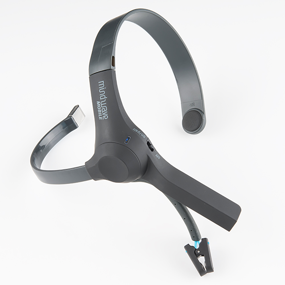
Taking it Apart
Pictured here is the MindWave headset. Nick Poole took one of these apart, so the insides of the headset are pictured here as well.
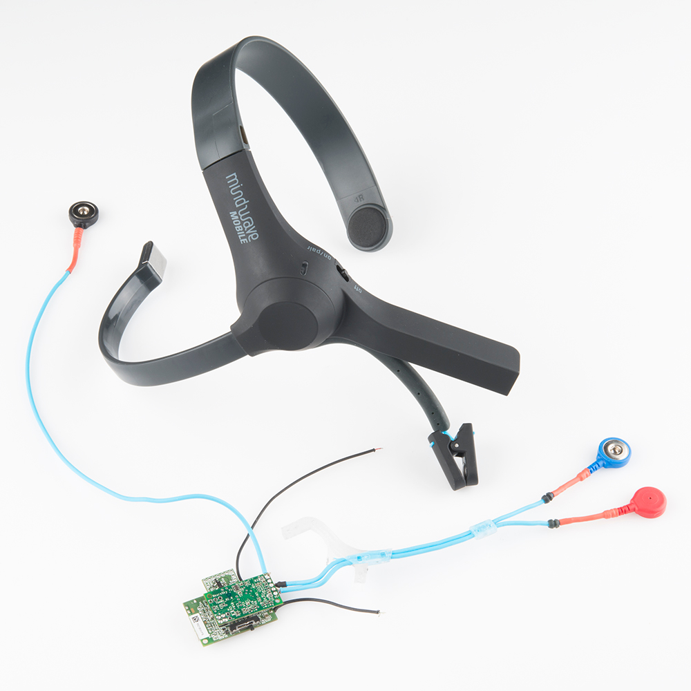
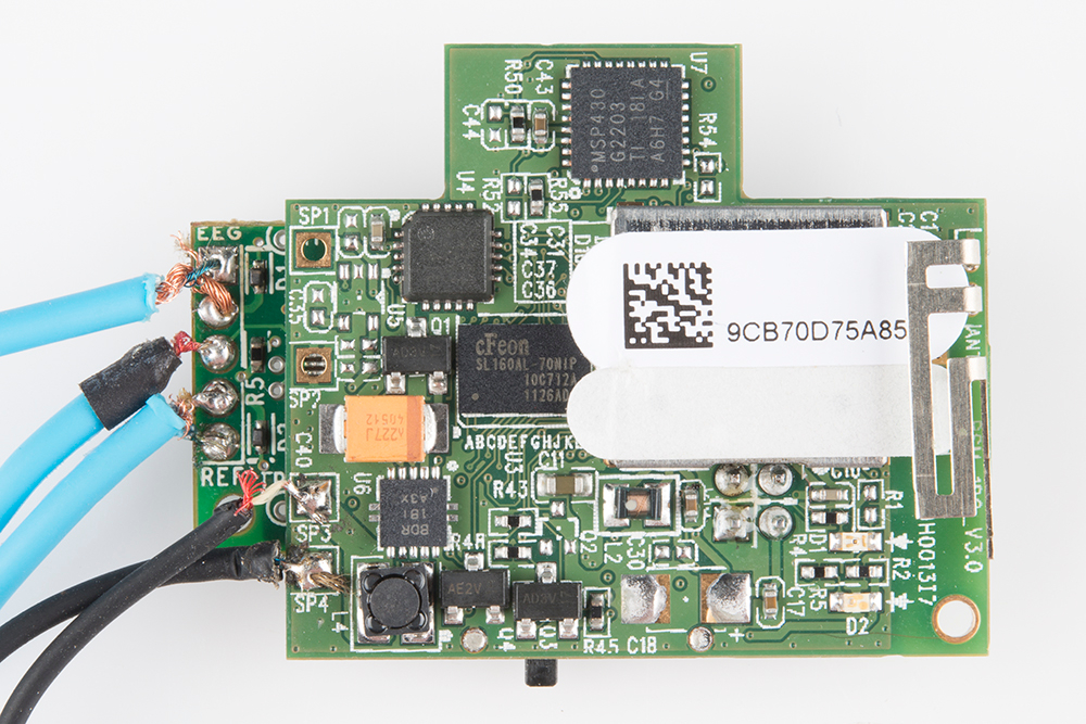
Here is a closeup of the internal circuitry. You may recognize the MSP430 hanging out at the top.
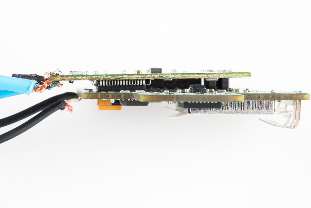
And, the backside....
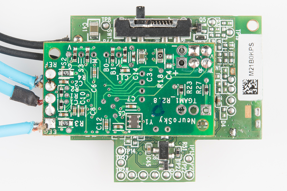
In between the two boards is an ASIC. The ASIC on the Neurosky calculates a value for Attention and Meditation. It also processes five types of brainwaves (more on this shortly) and sends out unitless values for each one. This unit measures eyeblinks too.
Gathering Materials
In order to interface with the MindWave, you'll need a few bits of hardware and software.
Hardware
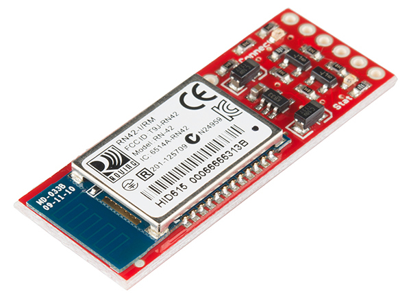
To interface with the MindWave, the RN-42 Bluetooth module was chosen. For this project, I created a custom PCB, however, you could also use a BlueSMiRF or a Bluetooth Mate. The Bluetooth module will be connected to an Arduino Uno to read in the data being transmitted wirelessly.
Once you've decided on which hardware you'll be using, connect everything. Again, the Bluetooth Basics and BlueSMiRF tutorials should cover how to do this extensively.
Software
You’ll want to get some programs to be able to read data from and configure the RN42 Bluetooth module.
- X-CTU, CoolTerm, or another serial terminal program of your choice.
- RS232 Port Logger
If you are unfamiliar with serial terminal emulators, please check out our tutorial.
Firmware
Here is the firmware for the Arduino side of this project. If you are following along, you'll want to upload this to whichever Arduino board you are using.
language:c
///////////////////////////////////////////////////////////////
// Arduino Bluetooth Interface with Mindwave
// Sophi Kravitz edit 11-4
// Shane Clements edit 11-5
////////////////////////////////////////////////////////////////////////
#include <SoftwareSerial.h>     // library for software serial
SoftwareSerial mySerial(5, 6);  // RX, TX
int LED = 8;                    // yellow one
int LED1 = 7;                   //white one
int BAUDRATE = 57600;

// checksum variables
byte payloadChecksum = 0;
byte CalculatedChecksum;
byte checksum = 0;              //data type byte stores an 8-bit unsigned number, from 0 to 255
int payloadLength = 0;
byte payloadData[64] = {0};
byte poorQuality = 0;
byte attention = 0;
byte meditation = 0;

// system variables
long lastReceivedPacket = 0;
boolean bigPacket = false;
boolean brainwave = false;
void setup() {
  pinMode(LED, OUTPUT);
  pinMode(LED1, OUTPUT);
  digitalWrite(LED, HIGH);   // hello sequence
  delay(100);
  digitalWrite(LED, LOW);
  delay(100);
  Serial.begin(57600);       // Bluetooth
  delay(500);
  mySerial.begin(4800);      // software serial
  delay(500);
  mySerial.print("Communicating... ");
  mySerial.println();
}
byte ReadOneByte() {
   int ByteRead;
  // Wait until there is data
  while(!Serial.available());
  //Get the number of bytes (characters) available for reading from the serial port.
  //This is data that's already arrived and stored in the serial receive buffer (which holds 64 bytes)
  ByteRead = Serial.read();
  return ByteRead; // read incoming serial data
  }

unsigned int delta_wave = 0;
unsigned int theta_wave = 0;
unsigned int low_alpha_wave = 0;
unsigned int high_alpha_wave = 0;
unsigned int low_beta_wave = 0;
unsigned int high_beta_wave = 0;
unsigned int low_gamma_wave = 0;
unsigned int mid_gamma_wave = 0;

void read_waves(int i) {
  delta_wave = read_3byte_int(i);
  i+=3;
  theta_wave = read_3byte_int(i);
  i+=3;
  low_alpha_wave = read_3byte_int(i);
  i+=3;
  high_alpha_wave = read_3byte_int(i);
  i+=3;
  low_beta_wave = read_3byte_int(i);
  i+=3;
  high_beta_wave = read_3byte_int(i);
  i+=3;
  low_gamma_wave = read_3byte_int(i);
  i+=3;
  mid_gamma_wave = read_3byte_int(i);
}

int read_3byte_int(int i) {
  return ((payloadData[i] << 16) + (payloadData[i+1] << 8) + payloadData[i+2]);
}

void loop() {
  // Look for sync bytes
  // Byte order: 0xAA, 0xAA, payloadLength, payloadData,
  // Checksum (sum all the bytes of payload, take lowest 8 bits, then bit inverse on lowest
if(ReadOneByte() == 0xAA) {
if(ReadOneByte() == 0xAA) {
payloadLength = ReadOneByte();
if(payloadLength > 169) //Payload length can not be greater than 169
return;
payloadChecksum = 0;
      for(int i = 0; i < payloadLength; i++) {      //loop until payload length is complete
        payloadData[i] = ReadOneByte();             //Read payload
        payloadChecksum += payloadData[i];
      }
      checksum = ReadOneByte();                     //Read checksum byte from stream
      payloadChecksum = 255 - payloadChecksum;      //Take one’s compliment of generated checksum
      if(checksum == payloadChecksum) {
        poorQuality = 200;
        attention = 0;
        meditation = 0;
 }
     brainwave = false;
     for(int i = 0; i < payloadLength; i++) { // Parse the payload
          switch (payloadData[i]) {
          case 02:
            i++;
            poorQuality = payloadData[i];
            bigPacket = true;
            break;
          case 04:
            i++;
            attention = payloadData[i];
            break;
          case 05:
            i++;
            meditation = payloadData[i];
            break;
          case 0x80:
            i = i + 3;
            break;
          case 0x83:                         // ASIC EEG POWER INT
            i++;
            brainwave = true;
            byte vlen = payloadData[i];
            //mySerial.print(vlen, DEC);
            //mySerial.println();
            read_waves(i+1);
            i += vlen; // i = i + vlen
            break;
          }                                 // switch
        }                                   // for loop

        if(bigPacket) {
          if(poorQuality == 0){
          }
          else{                             // do nothing
           }
         }


            if(brainwave && attention > 0 && attention < 100) {
            mySerial.print("Attention value is: ");
            mySerial.print(attention, DEC);
            mySerial.println();
            mySerial.print("Delta value is: ");
            mySerial.print(delta_wave, DEC);
            mySerial.println();
            mySerial.print("Theta value is: ");
            mySerial.print(theta_wave, DEC);
      mySerial.println();
            mySerial.print("Low Alpha value is: ");
            mySerial.print(low_alpha_wave, DEC);
            mySerial.println();
            mySerial.print("High Alpha value is: ");
            mySerial.print(high_alpha_wave, DEC);
            mySerial.println();
            mySerial.print("Alertness value1 is: ");
            mySerial.print(low_beta_wave, DEC);
            mySerial.println();
            mySerial.print("Alertness value2 is: ");
            mySerial.print(high_beta_wave, DEC);
            mySerial.println();
            mySerial.print(low_gamma_wave, DEC);
            mySerial.println();
            mySerial.print(mid_gamma_wave, DEC);
            mySerial.println();
         }

          if(attention > 40){
            digitalWrite(LED1, HIGH);
          }
          else
            digitalWrite(LED1, LOW);
        }
        }
      }
Here is the Processing code, which interprets the data coming from the MindWave to the Arduino, and then gives you a visual representation of that data.
language:java
//Processing code to graph Attention values
//Comment out all of the lines after “if(brainwave && attention > 0 && attention < 100) {“
//Except for
//mySerial.print(attention, DEC);
// mySerial.println();
//This will print out ONLY an Attention value and a new line afterwards

// Graphing sketch by Tom Igoe
// Sophi Kravitz edit 11/8

 import processing.serial.*;
 Serial myPort;        // The serial port
 int xPos = 1;         // horizontal position of the graph
 void setup () {
 // set the window size:
 size(400, 300);
String portName = Serial.list()[1];         //[1]  println(Serial.list()) to find the ports
 myPort = new Serial(this, "COM16", 4800);  // make sure the Baud rate matches the Arduino code
 myPort.bufferUntil('\n');                  // Wait for newline character:
 background(0);                             // set inital background color: 0 = black, 255 = white
 }

void draw () {                              // everything happens in the serialEvent()
 }

 void serialEvent (Serial myPort) {
 String inString = myPort.readStringUntil('\n');

   if (inString != null) {                  // trim whitespace:
   inString = trim(inString);               // convert to an int and map to the screen height:
   float inByte = float(inString);
   inByte = map(inByte, 0, 100, 0, height); // take number from 0 to 100, and map it to 0 to height
   stroke(5,34,255);                        // draw the line:
   line(xPos, height, xPos, height - inByte);

   if (xPos >= width) {                     // at the edge of the screen, go back to the beginning:
   xPos = 0;
   background(0);
   }
   else {
   xPos++;                                  // increment the horizontal position:
   }
 }
 }
Configuring the Bluetooth Module
The RN42 module can be configured to behave in a variety of different ways. If you have never configured one of the RN Bluetooth modules, please read our BlueSMiRF Hookup Guide.
You can use any serial terminal you wish to configure the bluetooth module. For this project, I used my Android phone with an app called S2 Terminal for Bluetooth to configure the RN42. The configuration process went as so:
**Note: **If you are using the S2 Terminal program, you will need to type in ASCII and put a return after each command. Also, you only have 60 seconds after power up to enter the first command.
- To put the RN42 into COMMAND mode, type $$$ (NO carriage return). If successful, you will see “CMD”.
Type:
D+ carriage return. You will see the current configuration of the RN42.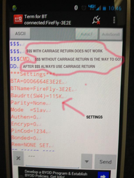
Type:
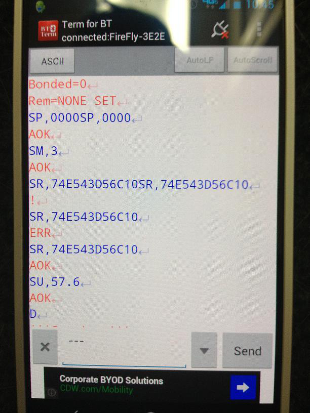
SP,0000+ carriage return. This will change the pincode from '1234' to '0000'. You will see “AOK” if this is done properly.- Type:
SM, 3+ carriage return. This will configure the RN42 to Auto-Connect Mode. Once the module is powered up, it will immediately look to connect (pair).You will see “AOK” if this is done properly. - Type:
SR,MAC ADDRESS+ carriage return. Insert the 12 digit address you copied from the MindWave Mobile. Look for AOK. If you don’t see AOK, you’ll have to retype the MAC address command. Now type:
SU,57.6+ carriage return. This will change the baud rate from 115200 to 57600.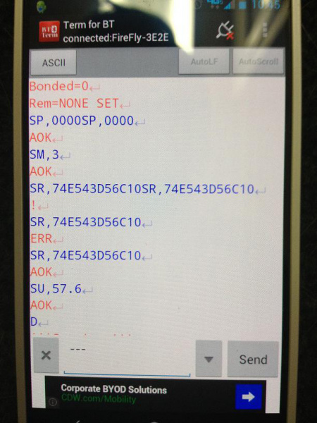
Type
D+ carriage return. Double check that the stored address is the Mac address you entered in step 5 and that it's configured to Auto, not Slave.Type:
---(three minus signs) + carriage return You should then see END.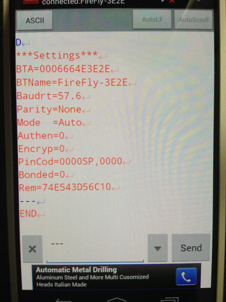


Turn the Mindwave on. The blue light flashes for a few moments, then it will pair with your hardware. You'll know that the Mindwave Mobile is paired because the blue light on the Mindwave Mobile is solid. If it is solid red, it is out of battery (AAA, lasts for about 8 hours).
Deciphering the MindWave Data
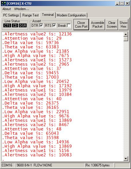
Using an FTDI basic, I was able to view the data coming in from the Arudino through my USB port. I used X-CTU to read the data. The Arduino code mentioned in the Gathering Materials section is mostly a combination of the Mindwave Mobile example code and Shane Clements’ massaging. The code is set up to print all of the digital data available out of the Mindwave Mobile. The data runs through the software serial port and is read easily on the X-CTU screen.
You can see unitless values for Delta, Theta, Alpha, Low Beta, High Beta and Gamma waves. The Mindwave’s ASIC also presents a calculated value for both Attention and Meditation. A number between 20 and 100 for Attention is normal, and a value above 40 means you are concentrating.
I was able to get repeatable values with the Attention value by counting backwards from 100 to1. We had a Bring A Hack dinner in Boulder, CO, and a few other people were able to make the Attention value rise by counting backwards from 100 to 1 also.
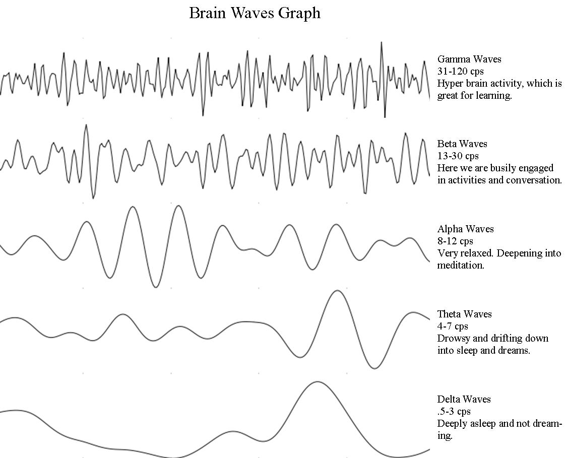
What is interesting is that the 5 types of brainwaves measured and reported originate from different parts of the brain. They also have extremely low amplitudes and frequencies.

- Gamma waves are oscillating waves with frequencies around 40 Hz, although they can be as high as 100 Hz and as low as 24 Hz. These originate from the thalamus (buried deep in the center of the brain) and are responsible for states of high attention and concentration.
- Beta waves are between 12 and 30 Hz and are the states associated with normal waking consciousness. These are emitted from the motor cortex, a region of the cerebral cortex, which is the outermost layer of tissue on the brain. Beta waves are split into three sections: Low Beta Waves (12.5-16 Hz, "Beta 1 power"); Beta Waves (16.5–20 Hz, "Beta 2 power"); and High Beta Waves (20.5-28 Hz, "Beta 3 power").
- Alpha waves originate at the Occipital lobe and have a frequency of 8-12Hz. These are most present when you are awake but are very drowsy or relaxed.
- Theta waves are oscillating waves that are located in the Hippocampus and are associated with dreaming. They are in the 4-7Hz range.
- Delta waves are associated with very deep, dreamless sleep cycles and are high amplitude waves, which have a 0 to 3Hz frequency. These waves emit from both the thalamus and the cortex.
The difference between these waves can be more easily understood when seen side-by-side.
If you used an Arduino with the code from the Gathering Materials section uploaded, you should be able to see these values printed out in X-CTU or the Serial terminal program of your choice.
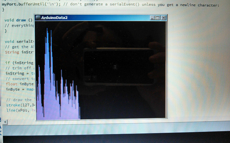
The Processing code found in the same section as the Arduino code can be used and modified to graph different values from the Arduino.
Resources and Going Further
The best results using the MindWave Mobile came when I looked at the processed Attention value. It was easy to see that when I (or anyone else) counted backwards from 100 to 1, the Attention values went up.
The deep brainwave values that I really wanted to see, such as Gamma, Beta, etc., were all over the place, and it was difficult to see any consistency in those values at all. In fact, the brainwave values varied the same when the unit was on the head as when off the head!
The Android app that comes with the Mindwave Mobile didn't work at all, I tried it on a few phones without success. Neurosky support thought that it was possible that my Android operating system was not compatible.
Overall, I don't think using the Neurosky Mindwave product yields any data that is very useable. I look forward to trying Neurosky’s next revision, and I am really looking forward to trying OpenBCI!
For more teardowns, check out these other offerings from SparkFun:
- Nest Thermostat Teardown
- Nest Protect Teardown
- LEAP Motion Teardown
- Google Glass Teardown (Sponsored by SFE)
To learn more about wireless technologies, visit some of these:
- RN-52 Audio Bluetooth Hookup Guide
- BC127 Audio Bluetooth Hookup Guide
- MetaWatch Teardown and Hookup
- WiFly Shield Hookup Guide
- Wireless Arduino Programming with Electric Imp
For more biometrics tutorials, check these out:
Or check out some of these blog posts for ideas: