H2OhNo!
This Tutorial is Retired!
This tutorial covers concepts or technologies that are no longer current. It's still here for you to read and enjoy, but may not be as useful as our newest tutorials.
 Nate
Nate 
Assembly
The H2OhNo! is a great beginner soldering kit and a great way to learn electronics and microcontrollers. It's very easy to put together and should take around 20 minutes or less. If you've never soldered before consider reading the How to Solder tutorial.
Before you dive in and begin soldering, please review the Remote Water Sensor and Remote LED sections below!
Kit Contents:
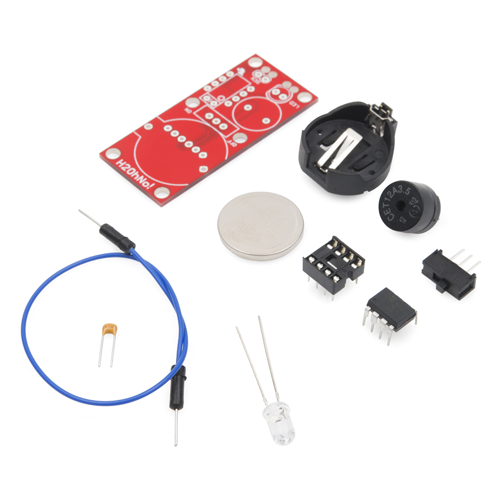
- Slide switch
- CR2032 coin cell battery and holder
- 0.1uF decoupling capacitor
- 8-pin DIP socket
- 8-pin ATtiny85 microcontroller
- 2kHz Piezo buzzer
- Super bright LED
- 1 jumper wire
Optional materials:
- Wire to locate the status LED off the board
- Heat shrink to cover up solder joints and strength connections
Remote Water Sensor
The water sensor works best when it is located a few inches from the board. This is accomplished by cutting the jumper wire in half and heat shrinking the two pins next to each other.
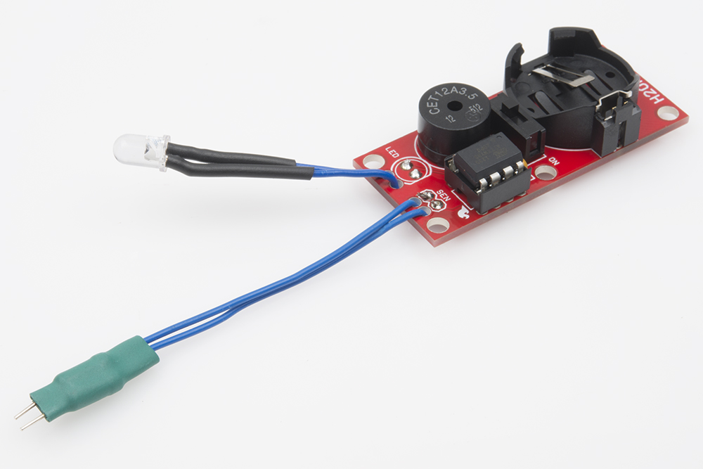
Remote LED
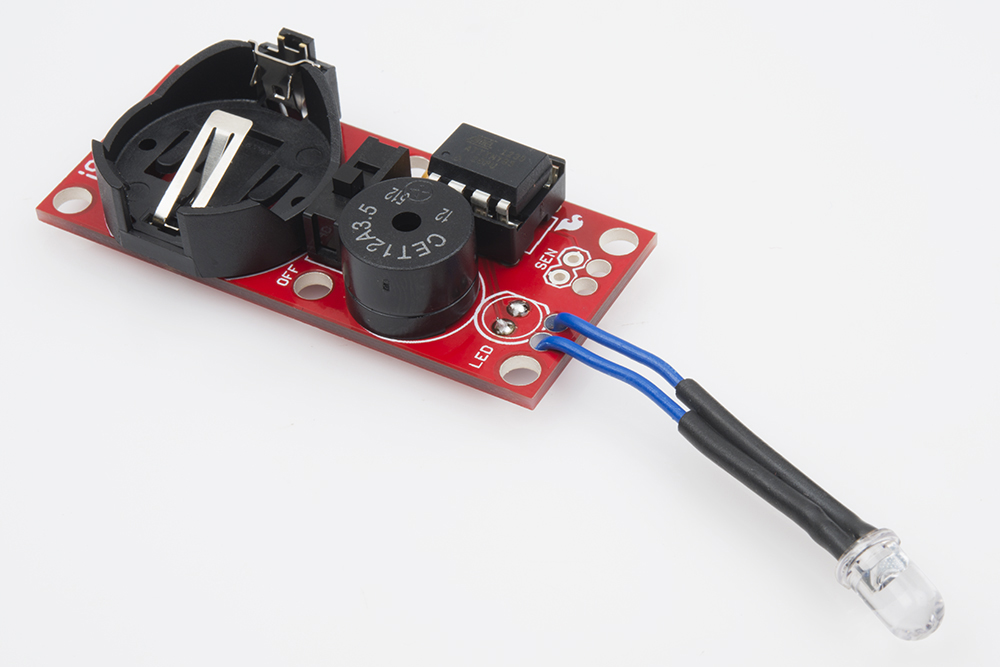
If the sensor will be installed in a remote location (like the inside of an underwater camera enclosure), you may want to locate the LED off the board to allow better visibility.
Stress Relief

There are two small holes located next to the sense and LED pins to relieve stress on the solder connection. Route the wires through these holes before soldering the wires in place.
Basic Assembly
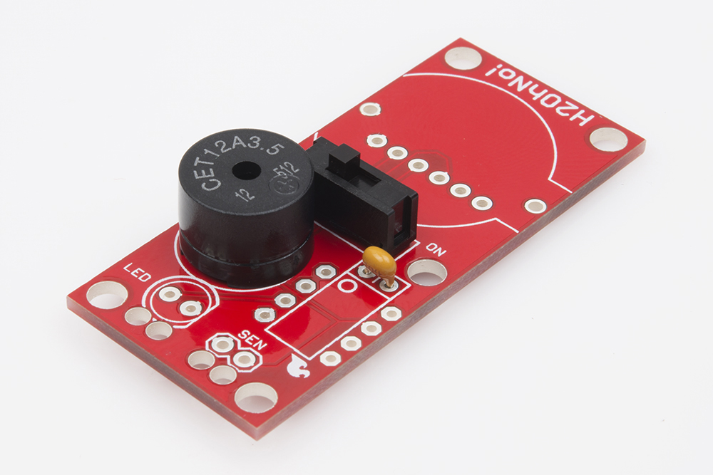
Step 1) All parts go into the top side of the PCB. Start with the 0.1uF capacitor, slide switch, and buzzer. None of these parts are polarized meaning they can go in either way. Using flush cutters, clip off any excess.
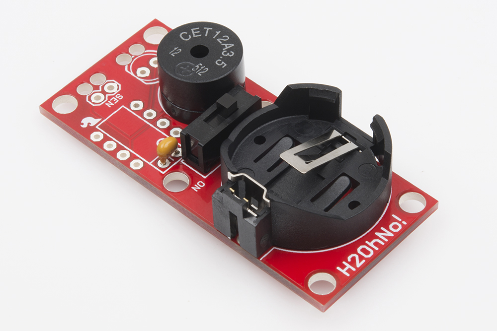
Step 2) Solder the battery holder in place. This part is polarized, but it's easy to see how it should fit; just be sure the holder lines up with the silkscreen outline. Don't insert the battery yet.


Step 3) Solder the 8-pin DIP socket in place. This part is polarized. Be sure the notch at the top of the socket is on the same end where the dot is. You can now insert the ATtiny85. Be sure to align the small dot on the ATtiny85 with the dot of the silkscreen and notch of the socket.
Step 4a) Now decide if you want the LED on or off the board. If you want the LED located on the board, line up the flat side of the LED with the flat line on the silkscreen. Solder the LED into place, and cut off any excess.
Step 4b) If you want the LED located off the board, cut two pieces of wire the same length. Strip both ends of the wires about 5mm. Cut the legs of the LED to about 5mm of exposed metal. Then, solder the wire to the short LED legs. Use heat shrink to cover up the joints. Now, insert the other end of the wires into the stress relief holes. Solder the wires into the LED pins. Remember that LEDs are polarized, so you'll need to solder the wire that extends from the flat side of the LED to the hole next to the flat line on the silkscreen. Once both wires are soldered, cut off any excess wire.
Step 5) To create the water sensor cut the pin off the end of each jumper wire. Strip 5mm from both wires. Insert the cut and stripped ends through the stress relief holes, then solder them into place. Use a piece of heat shrink to hold the pins next to each other.
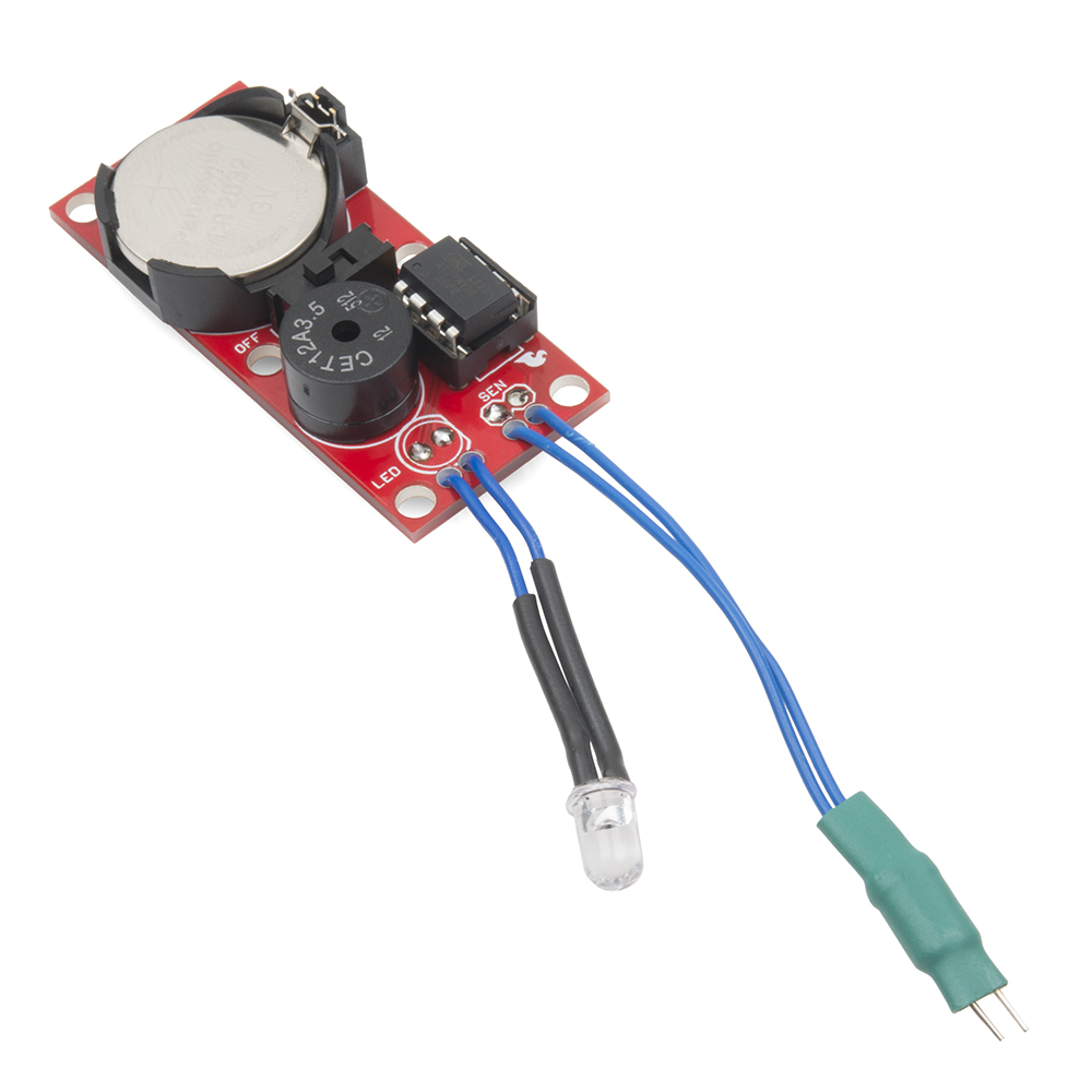
Step 6) Once you've got everything soldered together, insert the coin cell battery into the holder. The label on the battery goes up.
Flip the switch to on and you should hear the buzzer emit two short beeps. To test the water sensor, lick your finger, and touch the two pins. The LED should start blinking, and the alarm should go off. Congratulations! You've got a water alarm.
Installation
We recommend the board be located at least an inch away from where water might be. CR2032 batteries are wonderful in that they can take a lot of abuse, but the kit will last much longer in a nice, dry environment.
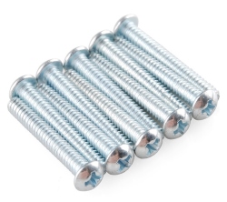
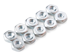
Use 4-40 screws and nuts to attach your kit to the surrounding environment.