H2OhNo!
This Tutorial is Retired!
This tutorial covers concepts or technologies that are no longer current. It's still here for you to read and enjoy, but may not be as useful as our newest tutorials.
 Nate
Nate 
Tiny Power
H2OhNo! is a water sensor alarm. When water is detected across the sense pins an alarm goes off and an LED starts blinking. If you've ever had a water heater explode or tried to create submersible electronics you know how important it is to be able to detect when water is around! You can buy one here.
Underneath the default function of H2OhNo! is a small but powerful development board for the ATtiny85 microcontroller. The board includes a buzzer, LED, a coin cell battery, and the ability to detect analog and digital sensors. This mixture of create a great low-cost tool to learn how to program and how to sense things!
Please note that this kit is not a professional water sensor kit and should not be used in crucial or life support applications. It's a great educational kit and can be used for a large number of applications including sensing when water has gotten too high or two low (like in a fish tank), or it can be programmed to detect an analog voltage and turn on an LED when the voltage has gotten too low (like a low battery indicator).
Suggested Reading
Before going further with this guide, you should be familiar with the topics covered in these tutorials:
Assembly
The H2OhNo! is a great beginner soldering kit and a great way to learn electronics and microcontrollers. It's very easy to put together and should take around 20 minutes or less. If you've never soldered before consider reading the How to Solder tutorial.
Before you dive in and begin soldering, please review the Remote Water Sensor and Remote LED sections below!
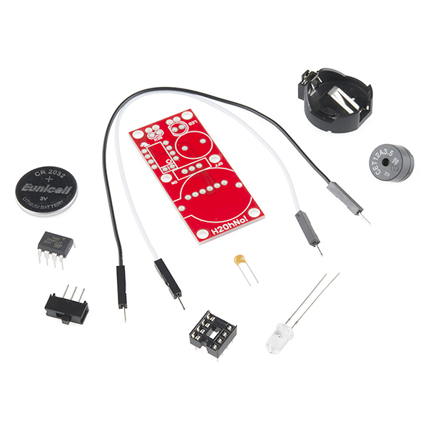
Kit Contents:
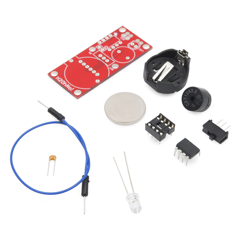
- Slide switch
- CR2032 coin cell battery and holder
- 0.1uF decoupling capacitor
- 8-pin DIP socket
- 8-pin ATtiny85 microcontroller
- 2kHz Piezo buzzer
- Super bright LED
- 1 jumper wire
Optional materials:
- Wire to locate the status LED off the board
- Heat shrink to cover up solder joints and strength connections
Remote Water Sensor
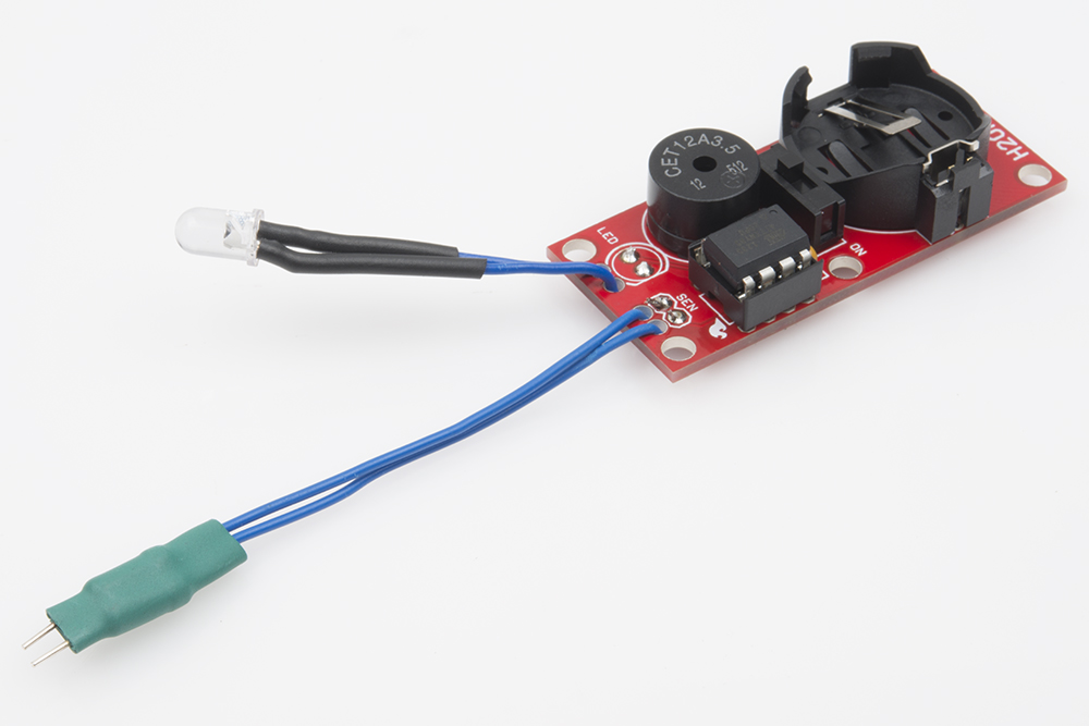
The water sensor works best when it is located a few inches from the board. This is accomplished by cutting the jumper wire in half and heat shrinking the two pins next to each other.
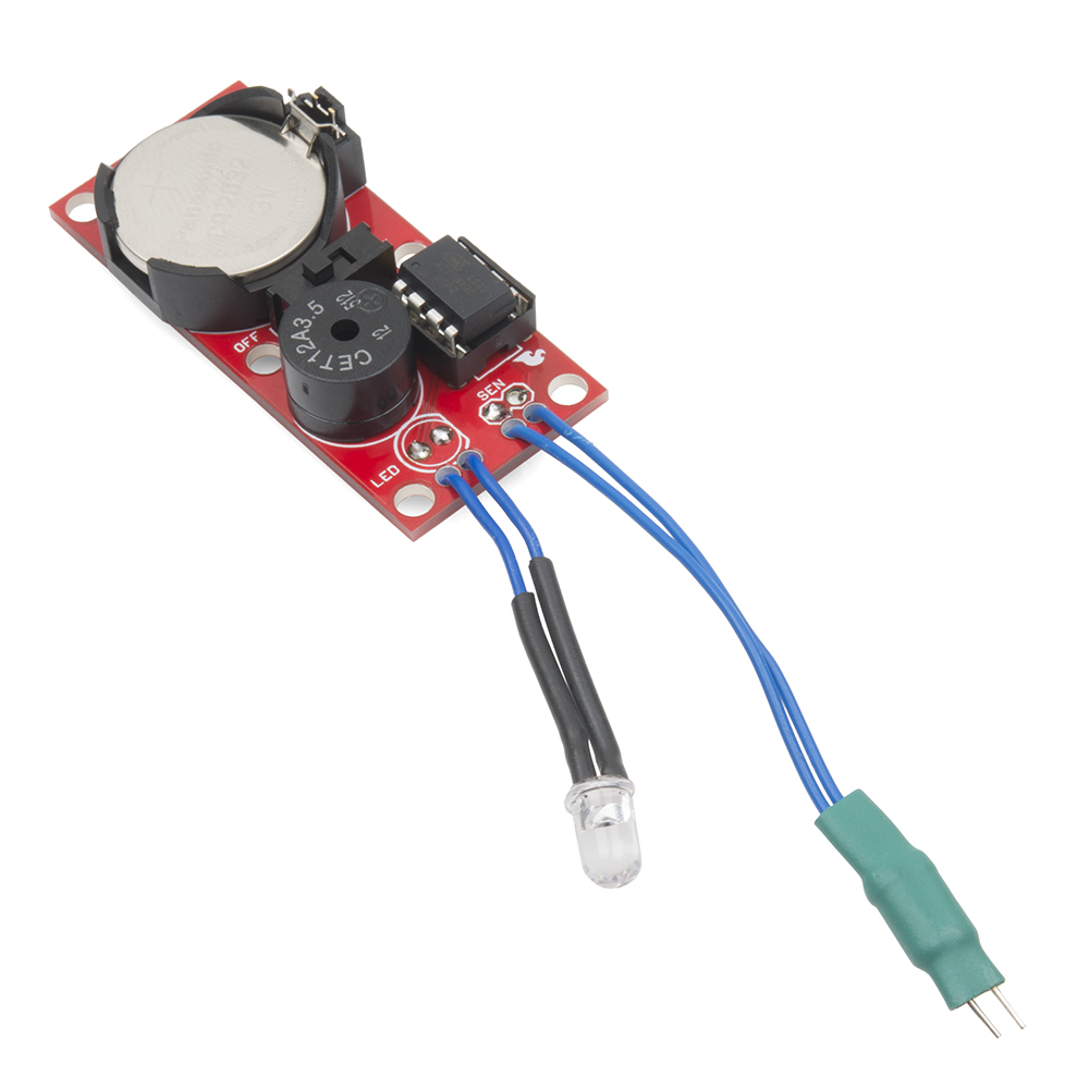
Remote LED
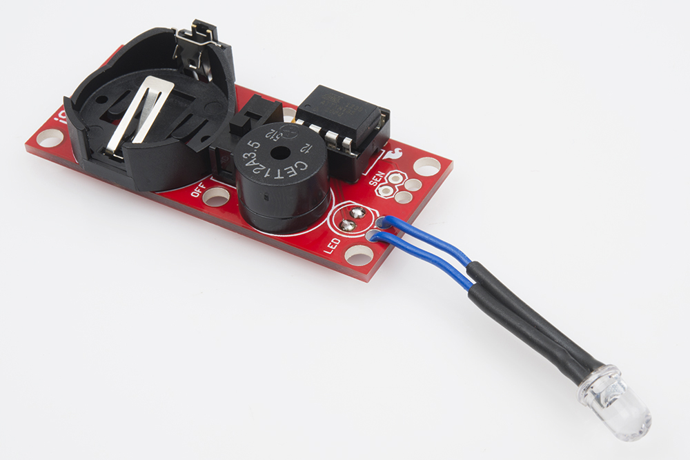
If the sensor will be installed in a remote location (like the inside of an underwater camera enclosure), you may want to locate the LED off the board to allow better visibility.
Stress Relief

There are two small holes located next to the sense and LED pins to relieve stress on the solder connection. Route the wires through these holes before soldering the wires in place.
Basic Assembly
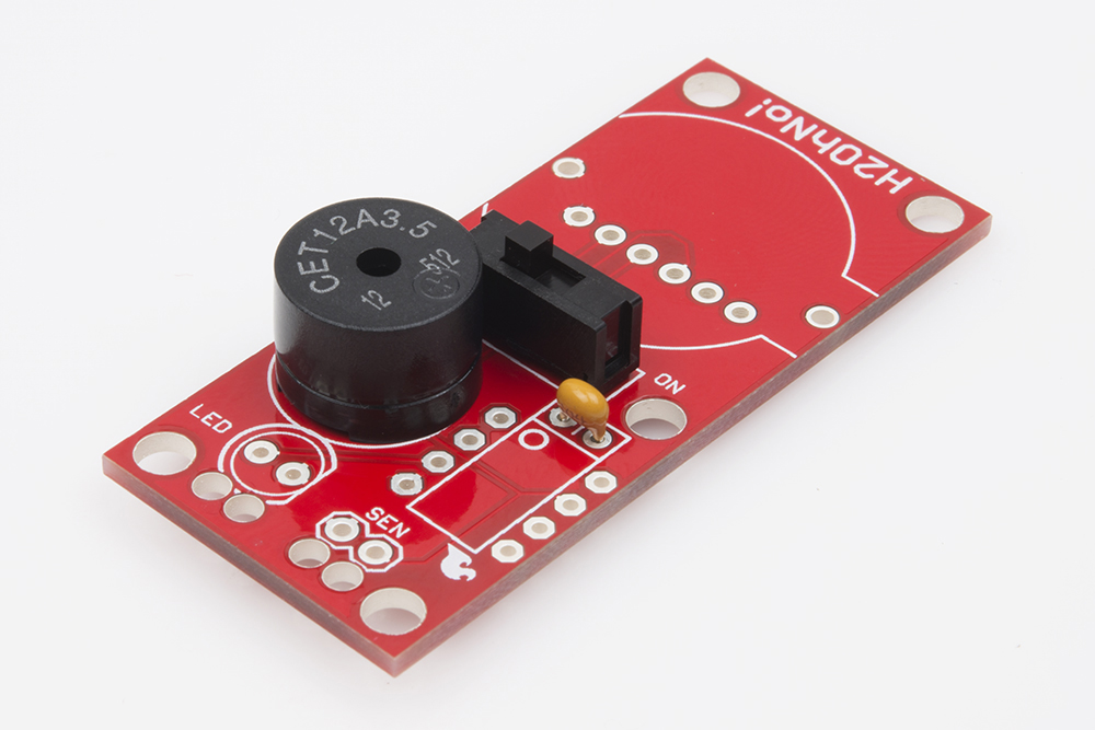
Step 1) All parts go into the top side of the PCB. Start with the 0.1uF capacitor, slide switch, and buzzer. None of these parts are polarized meaning they can go in either way. Using flush cutters, clip off any excess.
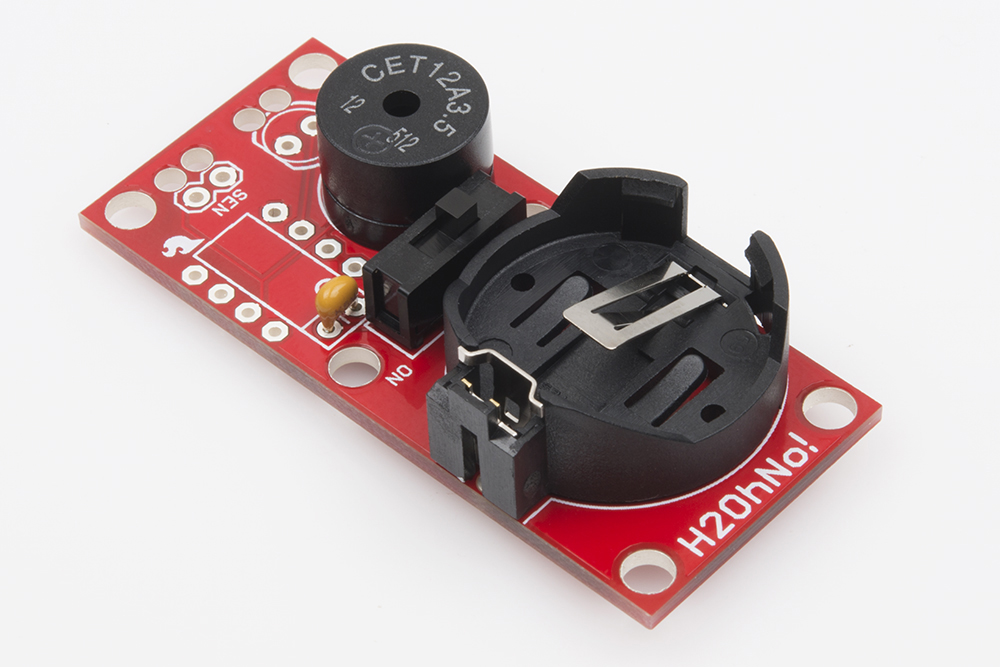
Step 2) Solder the battery holder in place. This part is polarized, but it's easy to see how it should fit; just be sure the holder lines up with the silkscreen outline. Don't insert the battery yet.


Step 3) Solder the 8-pin DIP socket in place. This part is polarized. Be sure the notch at the top of the socket is on the same end where the dot is. You can now insert the ATtiny85. Be sure to align the small dot on the ATtiny85 with the dot of the silkscreen and notch of the socket.
Step 4a) Now decide if you want the LED on or off the board. If you want the LED located on the board, line up the flat side of the LED with the flat line on the silkscreen. Solder the LED into place, and cut off any excess.
Step 4b) If you want the LED located off the board, cut two pieces of wire the same length. Strip both ends of the wires about 5mm. Cut the legs of the LED to about 5mm of exposed metal. Then, solder the wire to the short LED legs. Use heat shrink to cover up the joints. Now, insert the other end of the wires into the stress relief holes. Solder the wires into the LED pins. Remember that LEDs are polarized, so you'll need to solder the wire that extends from the flat side of the LED to the hole next to the flat line on the silkscreen. Once both wires are soldered, cut off any excess wire.
Step 5) To create the water sensor cut the pin off the end of each jumper wire. Strip 5mm from both wires. Insert the cut and stripped ends through the stress relief holes, then solder them into place. Use a piece of heat shrink to hold the pins next to each other.
Step 6) Once you've got everything soldered together, insert the coin cell battery into the holder. The label on the battery goes up.
Flip the switch to on and you should hear the buzzer emit two short beeps. To test the water sensor, lick your finger, and touch the two pins. The LED should start blinking, and the alarm should go off. Congratulations! You've got a water alarm.
Installation
We recommend the board be located at least an inch away from where water might be. CR2032 batteries are wonderful in that they can take a lot of abuse, but the kit will last much longer in a nice, dry environment.


Use 4-40 screws and nuts to attach your kit to the surrounding environment.
Reprogramming
H2OhNo! will work as a water alarm out of the box, but the real fun begins when you start to re-purpose the device!
H2OhNo is programmed using the Arduino IDE, but Arduino doesn't support the ATtiny series by default. To get Arduino to work with ATtiny microcontrollers you need to install a David Mellis' mod. Checkout the AVR Tiny Programmer tutorial for a full description of how to get the drivers and software setup.
Programming the ATtiny
Once you've got the Arduino IDE configured, we need to get our new code onto the ATtiny. The H2OhNo! development board was designed to be programmed with the Tiny AVR Programmer (originally designed by David Mellis - he's a wizard).
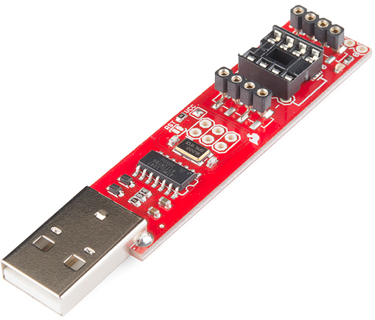
To load a new sketch onto the ATtiny, remove the 8-pin DIP from the H2OhNo!, and insert it into the DIP socket on the Tiny AVR Programmer. Plug the programmer into your computer's USB port. Select the ATtiny85 (internal 8MHz clock) from the Tools > Board menu, then hit upload. If you plan to use SoftwareSerial with your ATtiny, you will need to increase the internal clock to 8MHz by setting the fuse bits through the Burn Bootloader function. See Configuring the ATtiny to run at 8MHz on David's tutorial for more information.
Hardware Connections
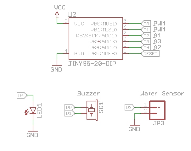
When loading new code you'll need to know where each pin is connected. This simplified schematic should help. You can also grab the schematic here. Be sure to checkout the H2OhNo! github repo for the open source hardware design files, as well as the example firmware.
Thank you David Mellis and Mark Sproul for building ATtiny support into the Arduino IDE!
Blink and Annoy
Now that you've got your programmer setup and working we can load fun new code onto the H2OhNo!.
Basic Blink Firmware
Basic Blink demonstrates how to blink the LED and make some noise. It's a great starting point. Copy and paste this code into the Arduino IDE, and reprogram your ATtiny.
language:c
//Pin definitions for ATtiny
const byte buzzer1 = 0;
const byte buzzer2 = 1;
const byte statLED = 4;

void setup()
{
  pinMode(buzzer1, OUTPUT);
  pinMode(buzzer2, OUTPUT);
  pinMode(statLED, OUTPUT);
}

void loop()
{
  digitalWrite(statLED, HIGH);
  alarmSound();
  delay(1000);

  digitalWrite(statLED, LOW);
  alarmSound();
  delay(1000);
}

//This is just a unique (annoying) sound we came up with, there is no magic to it
//Comes from the Simon Says game/kit actually: https://www.sparkfun.com/products/10547
//250us to 79us
void alarmSound(void)
{
  // Toggle the buzzer at various speeds
  for (byte x = 250 ; x > 70 ; x--)
  {
    for (byte y = 0 ; y < 3 ; y++)
    {
      digitalWrite(buzzer2, HIGH);
      digitalWrite(buzzer1, LOW);
      delayMicroseconds(x);

      digitalWrite(buzzer2, LOW);
      digitalWrite(buzzer1, HIGH);
      delayMicroseconds(x);
    }
  }
}
Original H2OhNo! Firmware
If you're reprogramming the ATtiny you may want to get back to the original code that shipped with the kit. Grab the latest code by going to the H2OhNo! github repo. Click 'raw', then copy and paste the code into Arduino.
Annoy-A-Tron Firmware
We know you will eventually come across the idea of an Annoy-a-tron. The original Annoy-A-Tron was created by Think Geek, and everyone knows how annoying a low-battery beep of a fire alarm can be. This is a very basic Annoy-A-Tron example that will beep every 5 minutes. We intentionally didn't build in low-power control so that if you happen to use this code you will only annoy your enemy for a few hours before the coin cell battery gives out.
language:c
//Pin definitions for ATtiny
const byte buzzer1 = 0;
const byte buzzer2 = 1;

void setup()
{
  pinMode(buzzer1, OUTPUT);
  pinMode(buzzer2, OUTPUT);
}

void loop()
{
  alarmSound();

  delay((long)1000 * 60 * 5); //5 minute delay
}

//This is just a unique (annoying) sound we came up with, there is no magic to it
//Comes from the Simon Says game/kit actually: https://www.sparkfun.com/products/10547
//250us to 79us
void alarmSound(void)
{
  // Toggle the buzzer at various speeds
  for (byte x = 250 ; x > 70 ; x--)
  {
    //for (byte y = 0 ; y < 3 ; y++)
    for (byte y = 0 ; y < 1 ; y++) //Slightly modified to be a shorter beep
    {
      digitalWrite(buzzer2, HIGH);
      digitalWrite(buzzer1, LOW);
      delayMicroseconds(x);

      digitalWrite(buzzer2, LOW);
      digitalWrite(buzzer1, HIGH);
      delayMicroseconds(x);
    }
  }
}
Creating projects to prank people is a fantastic way to learn electronics! Annoying them with incessant beeping is an ok start, but consider getting a lot more creative with your pranks.
Low-Power ATtiny
The firmware behind H2OhNo! is simple in theory and long in practice. We need to establish that when water is present then sound the alarm. But what do we do for the weeks and months when there is no water detected? Let's go to sleep and save power!
We've written some lengthier tutorials on getting the ATmega328 into very low power sleep. In this tutorial we will show you how to get the ATtiny into sleep mode as well.
Under normal conditions the ATtiny will consume 10-12mA running at 8MHz. Assuming the CR2032 battery contains 200mAh, that gives us (200mAh / 20mA) 10 hours of run time. Pretty good. But what if I told you I could get you 4,000 hours?
Watchdog Sleepy Time
The ATtiny can reach about 1uA in low-power sleep. Because we only need to periodically check for water let's put the ATtiny into sleep and wake it up every once and awhile.
A watchdog timer is good for two things:
- A watchdog can reset the processor when it gets locked into an endless loop - also known as going off into the weeds. This is a good way to protect a project needs to run all the time without user intervention. If the device ever gets locked up, the watchdog can cause the system to reset and (hopefully) return to regular operation.
- A watchdog can wake the processor from deep sleep. When we put a microcontroller into deep sleep, we can use the watchdog timer as an interrupt, causing the processor to return to normal 8MHz (without a full reset).
The watchdog is just a counter. When that counter gets to the size the user specifies, the processor will either reset or an interrupt will fire. Reset can be useful (as explained above), but an interrupt is what we need.
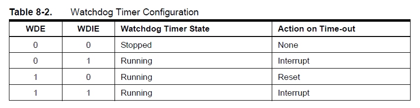
This table is key to the whole operation. If the watchdog is enabled (WDE) and the watchdog interrupt enable (WDIE) is not set, then the processor will reset. However, if the interrupt enable is set (WDIE = 1), then an interrupt occurs. As long as we set WDIE before we go to sleep, we'll wake up from an interrupt, and the program will continue from the point in the code where the sleep command was issued.
Here's the program operation we're aiming for:
- Go to sleep for a few seconds
- When the watchdog counter overflows use the interrupt to wake us up (not reset)
- Once awake, take a analog reading to check for water
- If there's no water, go back to sleep until the watchdog wakes us up again
Additional information about how to configure the watchdog timer can be found on the AVR Libc page on sleep.h. While sleep.h is good for getting us to sleep, it was Lab III's tutorial that provided the code that allows us to use the watchdog without resetting.
Here's the basic code that puts the ATtiny to sleep in the main loop():
language:c
setup_watchdog(6); //Setup watchdog to go off after 1sec
sleep_mode(); //Go to sleep! Wake up 1sec later and check water
Putting the ATtiny to sleep for a second then waking up and doing something means it will be at 0.250mA for 1sec and 10mA for 0.0001 second. Overall, this is much lower power than the original 10mA.
But we can go even lower! There are a few peripherals that also use power, namely the analog to digital converter. Because we will not be doing any ADC while sleeping, we can shut it down as well:
language:c
void loop()
{
    ADCSRA &= ~(1<<ADEN); //Disable ADC, saves ~230uA
    setup_watchdog(6); //Setup watchdog to go off after 1sec
    sleep_mode(); //Go to sleep! Wake up 1sec later and check water
    ADCSRA |= (1<<ADEN); //Enable ADC

    //Now check for water!
    checkForWater();
}
This is basically how H2OhNo! works. Power everything off, go to sleep, wakeup, do something useful (check for water), go back to sleep. By disabling the ADC during sleep, we can get the sleep current consumption down to 5uA! That's 0.005mA, or 2000 times lower than our original rate.
Remember that while the ATtiny is doing work (checking for water or making noise or blinking an LED) it will use the normal 10mA while it's awake. So between sleeping at 0.005mA and doing work every second at 10mA, on average we found the H2OhNo! uses about 50uA. That means on a 200mAh coin cell we should expect the board to run for (200mAh / 0.050mA = ) 4,000 hours or about 167 days.
The H2OhNo! will wake up every second and check for water. This is probably far more often than a real-world application needs. The longest period the watchdog can be configured to fire is 8 seconds. To sleep for longer periods of time and squeeze even longer battery life from your board, try using a counter within the watchdog interrupt:
language:c
//This runs each time the watch dog wakes us up from sleep
ISR(WDT_vect) {
  watchdog_counter++;
}

void loop()
{
  sleep_mode(); //Go to sleep!

  if(watchdog_counter > 30)
  {
    watchdog_counter = 0;

    alarmSound(); //Make noise!!
    digitalWrite(buzzer1, LOW);
    digitalWrite(buzzer2, LOW);
  }
}
This will wake the board up every second but immediately go back to sleep until 30 seconds have gone by.
Resources and Going Further
The ATtiny is a wonderful simple workhorse. With a coin cell battery and low-power sleep modes you can create some really amazing projects. For your next project consider building:
- An intrusion detection system
- A temperature alarm for a reptile habitat
- Use the internal EEPROM to datalog 512 light levels
- Count the number of times your front door is opened
Resources
- H2OhNo! schematic
- Water alarm example firmware
- The open source board files are available on the H2OhNo! github repo