GPS Geo-Mapping at the Push of a Button
 Brandon J. Williams
Hardware Hookup
This part of the build will require some assembly (but that's what we're all really here for anyway). Since most of our components carry over from the simple push button GPS tracker tutorial, we only have a few additional parts to assemble. Now, if you're fresh to the GPS tracker projects you don't have to worry. We'll run through all of it again anyway.
Assembly
Push Button Wiring
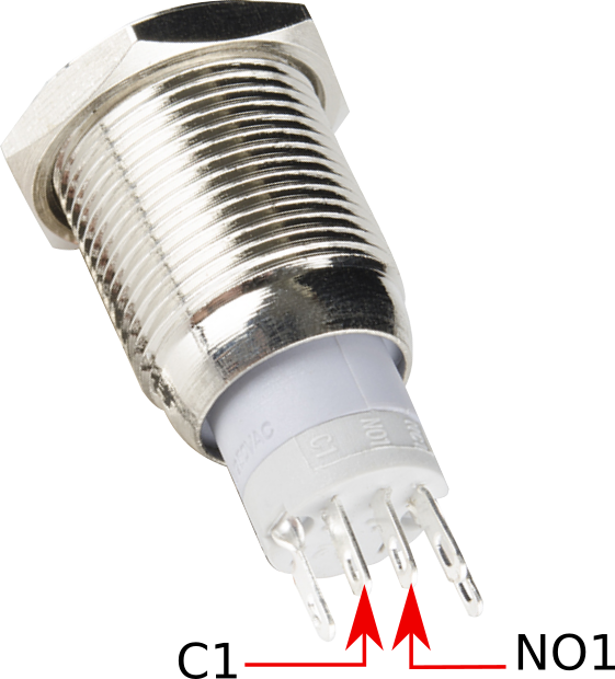
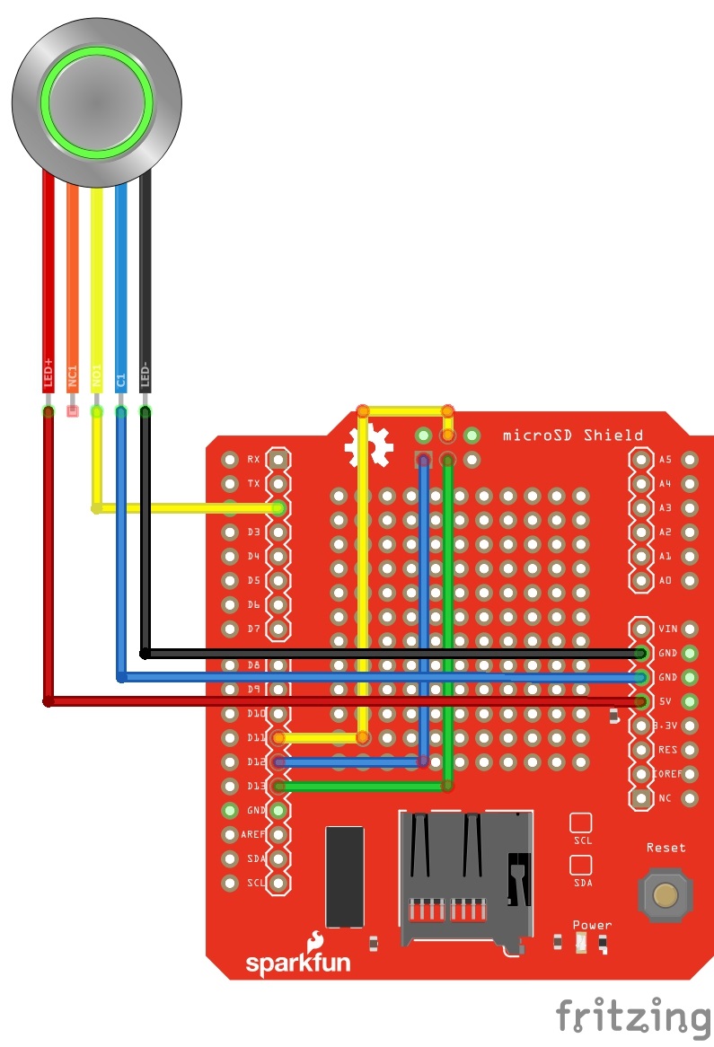
Our push button will be rather straightforward. The table below shows the connections between the button and our Turbo via the microSD shield.
| Button Pin | RedBoard Pin |
|---|---|
| + | 5V |
| - | GND |
| C1 | GND |
| NO1 | Digital Pin 2 |
MicroSD Shield
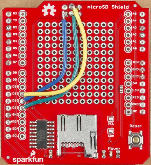
The first step would be to solder our break away headers to the pins aligning with the Redboard Turbo female headers. We also need to solder the 2x3 Female ISP connector to the bottom of the microSD shield. We'll use that ISP header for a modification needed for communication.
I mentioned earlier that there was a special note for communication between the Turbo and our microSD shield. The best explanation currently is there is a naming difference in libraries and the SERCOM tools used on the Turbo. We can easily circumvent the issue by hardwiring our Digital Pins (13 -11) to the ISP header found on all our Redboards.
I discovered this issue when I was running a simple datalogger sketch and I kept getting a false return from the SD.begin() call. After making these hotwiring corrections, I got correct functionality.
Once we're done with the headers, we can move on to connecting our pushbutton. Following the table mentioned earlier, we need to solder our wires to the microSD shield. There are PTH holes alongside all the header holes to solder to. We're looking for these specific pins:
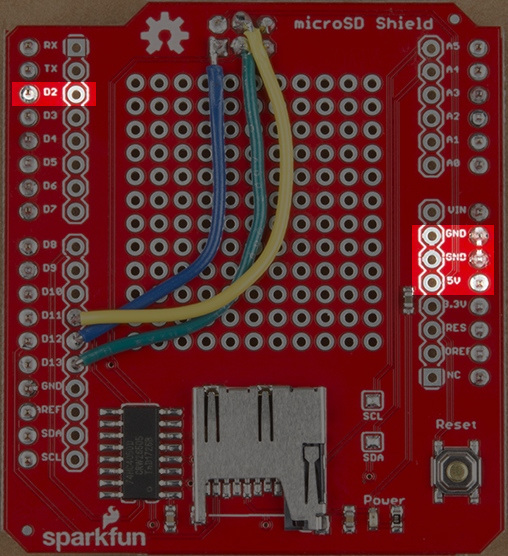
| Button Pin | microSD Shield Pin |
|---|---|
| + | 5V |
| - | GND |
| C1 | GND |
| NO1 | Digital Pin 2 |
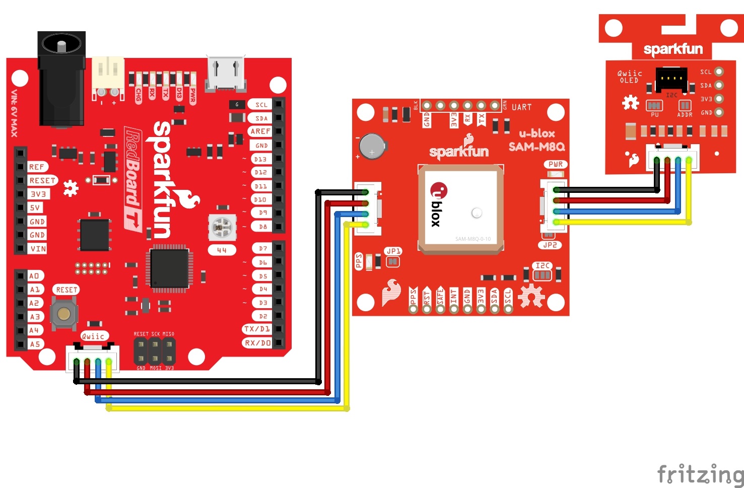
Reference Diagrams
Optional Assembly
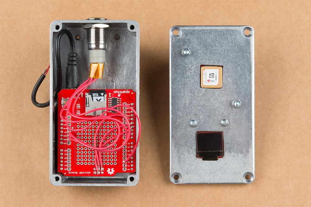
Aluminum Case
We do have an aluminum case added to the required materials list. While it is optional, it provides a sturdy case for practical application purposes. If you purchase the case then you'll have to make extra modifications. We'll need to drill screw holes and protuding areas for our OLED screen and GPS chip antenna.