Getting Started with MicroMod
 Nate
Nate Introduction
MicroMod is a compact interface to connect a microcontroller to various peripherals. You can generally think of the MicroMod system as a ‘brain’ plugging into a ‘carrier board’.
A MicroMod processor board is approximately 22x22mm and can insert into any MicroMod carrier board. A small screw holds the processor board in place. Whereas the original M.2 standard was designed for swapping out peripherals (user could change one solid state hard drive to a larger one) the MicroMod standard is designed for swapping out controllers (user can start with a powerful processor and then change to a low power controller to extend battery life).
Suggested Reading
If you aren't familiar with the MicroMod ecosystem, we recommend reading here for an overview.
| MicroMod Ecosystem |
If you aren’t familiar with the following concepts, we recommend checking out these tutorials before continuing.
Serial Peripheral Interface (SPI)
Pulse Width Modulation
Logic Levels
I2C
How Does It Work?
The MicroMod standard leverages the M.2 connector and specification to increase the availability of parts and reduce the cost of the connector. All MicroMod ‘brains’ share a common pinout. For example, the I2C pins for the MicroMod ESP32 are in the same position as the I2C pins on the MicroMod Artemis.
A variety of MicroMod carrier boards give the user access to different technologies. Because the MicroMod connector is standardized, the controller can be easily and quickly swapped out as processing power, power consumption, and wireless connectivity. For example, a user may start with the MicroMod Artemis and a RFID carrier board. They then might decide they need WiFi for their project. Swapping to the MicroMod ESP32 allows the user to instantly add WiFi capabilities without changing the underlying hardware.
The MicroMod interface is defined as follows:
Hardware Overview
What Connector and Key Does MicroMod Use?
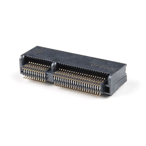
MicroMod uses the common M.2 connector. This is the same connector found on modern motherboards and laptops. We recommend the connector with 4.2mm height.
 |
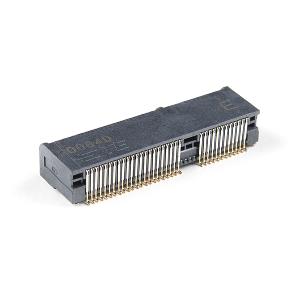 |
| M.2 Connector Socket View | M.2 Connector View from Back |
TE makes the 2199230-4 that is widely available and for reasonable cost (1k budgetary pricing is $0.56). You can also order the MicroMod DIY Carrier Kit that includes 5 of the connector, screw, and reflow-able standoff.
There are various locations for the plastic ‘key’ on the M.2 connector to prevent a user from inserting an incompatible device. The MicroMod standard uses the ‘E’ key but diverges from the M.2 standard by moving the mounting screw 4mm to the side. The ‘E’ key is fairly common so a user could insert a M.2 compatible Wifi module but because the screw mount doesn’t align, the user would not be able to secure an incompatible device into a MicroMod carrier board.
What is a Processor Board?
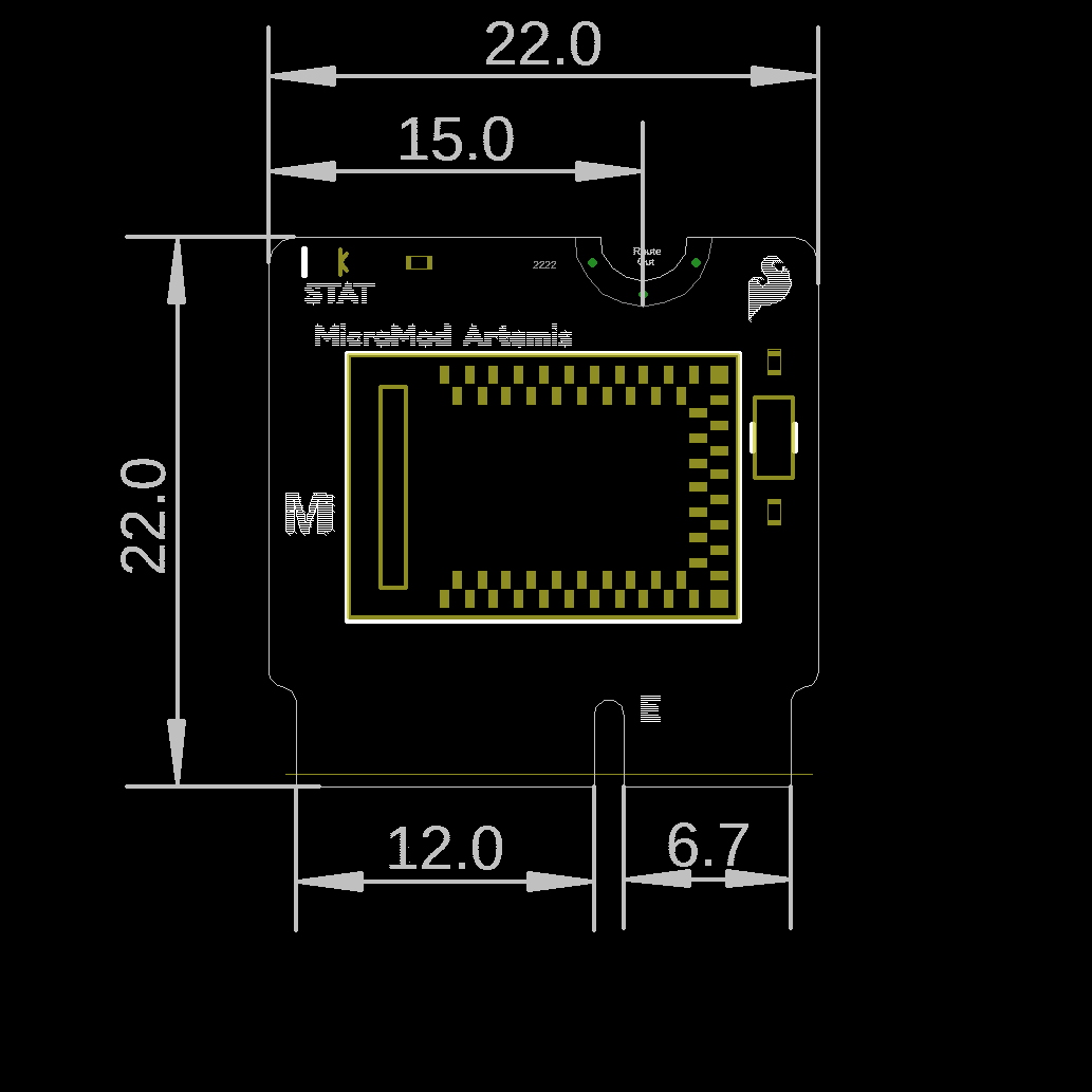
Each processor board is approximately 22x22mm and has a microcontroller or processor on it. The pins on the processor are brought to the card edge to match the MicroMod pinout specification.
Every processor board is expected to need only USB D+/- to be programmed. This means that a processor that does not have built-in USB Support must have it added. For example: the Artemis Processor board has the CH340E added to provide serial programming support.
Every processor board is expected to have one on-board status LED that is not routed to the board edge.
Note: The MicroMod spec moves the screw position from the board's center line to 4mm right-of-center. This is meant to prevent incorrect mixing of a growing number of devices that use the M.2 connector (such as WiFi cards, SSDs, cellular modems, etc) and MicroMod devices. While a user could insert a WiFi card into a SparkFun data logging carrier board the screw holes would not line up making it obvious the devices don't work together.
The MicroMod spec may incorporate larger sizes in the future, and users are welcome to create their own processor boards, but note that the standoff hole on most carrier boards will be located to fit the 2222 MicroMod key.
What is the MicroMod Pinout?
The MicroMod interface is defined as follows:

Click on the image for a closer view of the graphical datasheet.
Note that the M.2 connector pins on opposing sides are offset from each other as indicated by the bottom pins. It's not as apparent in the table further below since it is not offset. As a result, one row for the bottom pins are "Not Connected".
Below is the general MicroMod interface pinout for v1.0 processor and carrier boards.
Not all of the pins are guaranteed to be connected when using the MicroMod form factor. Please see the documentation specific to your processor board for more information.
| AUDIO | UART | GPIO/BUS | I2C | SDIO | SPI | Dedicated |
| Function | Bottom Pin |
Top Pin |
Function | ||||||
|---|---|---|---|---|---|---|---|---|---|
| (Not Connected) | 75 | GND | |||||||
| 3.3V | 74 | 73 | G5 / BUS5 | ||||||
| RTC_3V_BATT | 72 | 71 | G6 / BUS6 | ||||||
| SPI_CS1# | SDIO_DATA3 (I/O) | 70 | 69 | G7 / BUS7 | |||||
| SDIO_DATA2 (I/O) | 68 | 67 | G8 | ||||||
| SDIO_DATA1 (I/O) | 66 | 65 | G9 | ADC_D- | CAM_HSYNC | ||||
| SPI_CIPO1 | SDIO_DATA0 (I/O) | 64 | 63 | G10 | ADC_D+ | CAM_VSYNC | |||
| SPI COPI1 | SDIO_CMD (I/O) | 62 | 61 | SPI_CIPO (I) | |||||
| SPI SCK1 | SDIO_SCK (O) | 60 | 59 | SPI_COPI (O) | LED_DAT | ||||
| AUD_MCLK (O) | 58 | 57 | SPI_SCK (O) | LED_CLK | |||||
| CAM_MCLK | PCM_OUT | I2S_OUT | AUD_OUT | 56 | 55 | SPI_CS# | |||
| CAM_PCLK | PCM_IN | I2S_IN | AUD_IN | 54 | 53 | I2C_SCL1 (I/O) | |||
| PDM_DATA | PCM_SYNC | I2S_WS | AUD_LRCLK | 52 | 51 | I2C_SDA1 (I/O) | |||
| PDM_CLK | PCM_CLK | I2S_SCK | AUD_BCLK | 50 | 49 | BATT_VIN / 3 (I - ADC) (0 to 3.3V) | |||
| G4 / BUS4 | 48 | 47 | PWM1 | ||||||
| G3 / BUS3 | 46 | 45 | GND | ||||||
| G2 / BUS2 | 44 | 43 | CAN_TX | ||||||
| G1 / BUS1 | 42 | 41 | CAN_RX | ||||||
| G0 / BUS0 | 40 | 39 | GND | ||||||
| A1 | 38 | 37 | USBHOST_D- | ||||||
| GND | 36 | 35 | USBHOST_D+ | ||||||
| A0 | 34 | 33 | GND | ||||||
| PWM0 | 32 | 31 | Module Key | ||||||
| Module Key | 30 | 29 | Module Key | ||||||
| Module Key | 28 | 27 | Module Key | ||||||
| Module Key | 26 | 25 | Module Key | ||||||
| Module Key | 24 | 23 | SWDIO | ||||||
| UART_TX2 (O) | 22 | 21 | SWDCK | ||||||
| UART_RX2 (I) | 20 | 19 | UART_RX1 (I) | ||||||
| CAM_TRIG | D1 | 18 | 17 | UART_TX1 (0) | |||||
| I2C_INT# | 16 | 15 | UART_CTS1 (I) | ||||||
| I2C_SCL (I/0) | 14 | 13 | UART_RTS1 (O) | ||||||
| I2C_SDA (I/0) | 12 | 11 | BOOT (I - Open Drain) | ||||||
| D0 | 10 | 9 | USB_VIN | ||||||
| SWO | G11 | 8 | 7 | GND | |||||
| RESET# (I - Open Drain) | 6 | 5 | USB_D- | ||||||
| 3.3V_EN | 4 | 3 | USB_D+ | ||||||
| 3.3V | 2 | 1 | GND | ||||||
| Signal Group | Signal | I/O | Description | Voltage | Power | 3.3V | I | 3.3V Source | 3.3V |
|---|---|---|---|---|
| GND | Return current path | 0V | ||
| USB_VIN | I | USB VIN compliant to USB 2.0 specification. Connect to pins on processor board that require 5V for USB functionality | 4.8-5.2V | |
| RTC_3V_BATT | I | 3V provided by external coin cell or mini battery. Max draw=100μA. Connect to pins maintaining an RTC during power loss. Can be left NC. | 3V | |
| 3.3V_EN | O | Controls the carrier board's main voltage regulator. Voltage above 1V will enable 3.3V power path. | 3.3V | |
| BATT_VIN/3 | I | Carrier board raw voltage over 3. 1/3 resistor divider is implemented on carrier board. Amplify the analog signal as needed for full 0-3.3V range | 3.3V | |
| Reset | Reset | I | Input to processor. Open drain with pullup on processor board. Pulling low resets processor. | 3.3V |
| Boot | I | Input to processor. Open drain with pullup on processor board. Pulling low puts processor into special boot mode. Can be left NC. | 3.3V | |
| USB | USB_D± | I/O | USB Data ±. Differential serial data interface compliant to USB 2.0 specification. If UART is required for programming, USB± must be routed to a USB-to-serial conversion IC on the processor board. | |
| USB Host | USBHOST_D± | I/O | For processors that support USB Host Mode. USB Data±. Differential serial data interface compliant to USB 2.0 specification. Can be left NC. | |
| CAN | CAN_RX | I | CAN Bus receive data. | 3.3V |
| CAN_TX | O | CAN Bus transmit data. | 3.3V | |
| UART | UART_RX1 | I | UART receive data. | 3.3V |
| UART_TX1 | O | UART transmit data. | 3.3V | |
| UART_RTS1 | O | UART ready to send. | 3.3V | |
| UART_CTS1 | I | UART clear to send. | 3.3V | |
| UART_RX2 | I | 2nd UART receive data. | 3.3V | |
| UART_TX2 | O | 2nd UART transmit data. | 3.3V | |
| I2C | I2C_SCL | I/O | I2C clock. Open drain with pullup on carrier board. | 3.3V |
| I2C_SDA | I/O | I2C data. Open drain with pullup on carrier board | 3.3V | |
| I2C_INT# | I | Interrupt notification from carrier board to processor. Open drain with pullup on carrier board. Active LOW | 3.3V | |
| I2C_SCL1 | I/O | 2nd I2C clock. Open drain with pullup on carrier board. | 3.3V | |
| I2C_SDA1 | I/O | 2nd I2C data. Open drain with pullup on carrier board. | 3.3V | |
| SPI | SPI_COPI | O | SPI Controller Output/Peripheral Input. | 3.3V |
| SPI_CIPO | I | SPI Controller Input/Peripheral Output. | 3.3V | |
| SPI_SCK | O | SPI Clock. | 3.3V | |
| SPI_CS# | O | SPI Chip Select. Active LOW. Can be routed to GPIO if hardware CS is unused. | 3.3V | |
| SPI/SDIO | SPI_SCK1/SDIO_CLK | O | 2nd SPI Clock. Secondary use is SDIO Clock. | 3.3V |
| SPI_COPI1/SDIO_CMD | I/O | 2nd SPI Controller Output/Peripheral Input. Secondary use is SDIO command interface. | 3.3V | |
| SPI_CIPO1/SDIO_DATA0 | I/O | 2nd SPI Peripheral Input/Controller Output. Secondary use is SDIO data exchange bit 0. | 3.3V | |
| SDIO_DATA1 | I/O | SDIO data exchange bit 1. | 3.3V | |
| SDIO_DATA2 | I/O | SDIO data exchange bit 2. | 3.3V | |
| SPI_CS1/SDIO_DATA3 | I/O | 2nd SPI Chip Select. Secondary use is SDIO data exchange bit 3. | 3.3V | |
| Audio | AUD_MCLK | O | Audio master clock. | 3.3V |
| AUD_OUT/PCM_OUT/I2S_OUT/CAM_MCLK | O | Audio data output. PCM synchronous data output. I2S serial data out. Camera master clock. | 3.3V | |
| AUD_IN/PCM_IN/I2S_IN/CAM_PCLK | I | Audio data input. PCM syncrhonous data input. I2S serial data in. Camera periphperal clock. | 3.3V | |
| AUD_LRCLK/PCM_SYNC/I2S_WS/PDM_DATA | I/O | Audio left/right clock. PCM syncrhonous data SYNC. I2S word select. PDM data. | 3.3V | |
| AUD_BCLK/PCM_CLK/I2S_CLK/PDM_CLK | O | Audio bit clock. PCM clock. I2S continuous serial clock. PDM clock. | 3.3V | |
| SWD | SWDIO | I/O | Serial Wire Debug I/O. Connect if processor board supports SWD. Can be left NC. | 3.3V |
| SWDCK | I | Serial Wire Debug clock. Connect if processor board supports SWD. Can be left NC. | 3.3V | |
| ADC | A0 | I | Analog to digital converter 0. Amplify the analog signal as needed to enable full 0-3.3V range. | 3.3V |
| A1 | I | Analog to digital converter 1. Amplify the analog signal as needed to enable full 0-3.3V range. | 3.3V | |
| PWM | PWM0 | O | Pulse width modulated output 0. | 3.3V |
| PWM1 | O | Pulse width modulated output 1. | 3.3V | |
| Digital | D0 | I/O | General digital input/output pin. | 3.3V |
| D1/CAM_TRIG | I/O | General digital input/output pin. Camera trigger. | 3.3V | |
| General/Bus | G0/BUS0 | I/O | General purpose pins. Any unused processor pins should be assigned to Gx with ADC + PWM capable pins given priority (0, 1, 2, etc.) positions. The intent is to guarantee PWM, ADC and Digital Pin functionality on respective ADC/PWM/Digital pins. Gx pins do not guarantee ADC/PWM function. Alternative use is pins can support a fast read/write 8-bit or 4-bit wide bus. | 3.3V |
| G1/BUS1 | I/O | 3.3V | ||
| G2/BUS2 | I/O | 3.3V | ||
| G3/BUS3 | I/O | 3.3V | ||
| G4/BUS4 | I/O | 3.3V | ||
| G5/BUS5 | I/O | 3.3V | ||
| G6/BUS6 | I/O | 3.3V | ||
| G7/BUS7 | I/O | 3.3V | ||
| G8 | I/O | General purpose pin | 3.3V | |
| G9/ADC_D-/CAM_HSYNC | I/O | Differential ADC input if available. Camera horizontal sync. | 3.3V | |
| G10/ADC_D+/CAM_VSYNC | I/O | Differential ADC input if available. Camera vertical sync. | 3.3V | |
| G11/SWO | I/O | General purpose pin. Serial Wire Output | 3.3V |
Each pin on the M.2 connector is specified to have a given function. There are additional rules to the MicroMod specification to ensure cross platform compatibility. At the extreme case, a maximum of 49x GPIOs are supported. In general, MicroMod focuses on interface types and locations. For example, if a carrier board requires PWM capabilities then the carrier board should leverage pins 32 (aka PWM0) and 47 (aka PWM1) as these are most likely to support PWM.
Supported Interfaces:
- USB for programming and serial debug
- 2x Analog Dedicated
- 2x PWM Dedicated
- 2x Digital I/O Dedicated
- 12x GPIO
- 2x I2C
- 2x SPI
- 2x UART
- SDIO
- USB-HOST
- CAN
- SWD
- PDM / PCM / I2S
- Differential ADC
12x GPIOs may not sound like much but once all the other interfaces have been connected (UART, SPI, I2C, PWM, ADC) 12x GPIOs should cover most remaining applications.
Hardware Hookup
Below are the steps to connect your MicroMod boards together!
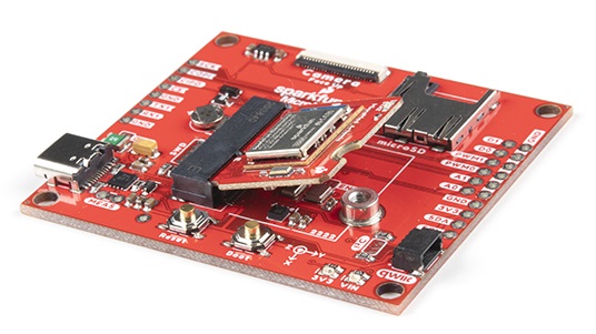
Connecting a Processor to a Carrier Board
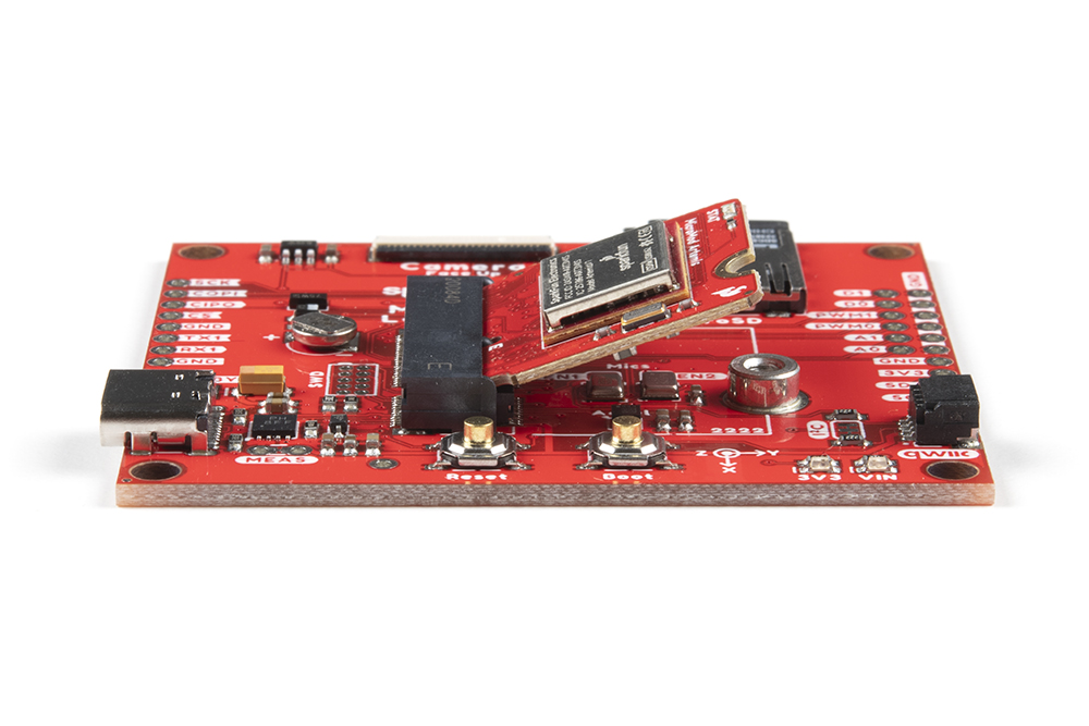
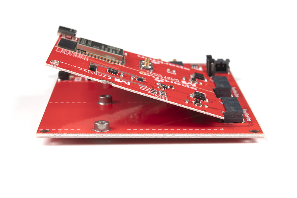
To get started with MicroMod, you'll need a processor board as well as a carrier board. Here we are using the Artemis MicroMod Processor Board with the Machine Learning Carrier Board. Align the top key of the MicroMod Artemis Processor Board to the screw terminal of the Machine Learning Carrier Board and angle the board into the socket. Insert the board at an angle into the M.2 connector.
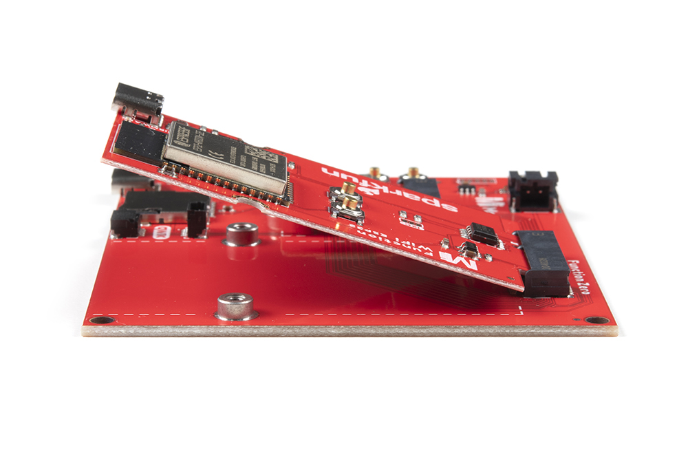
The Processor Board will stick up at an angle (at around 25°), as seen here:
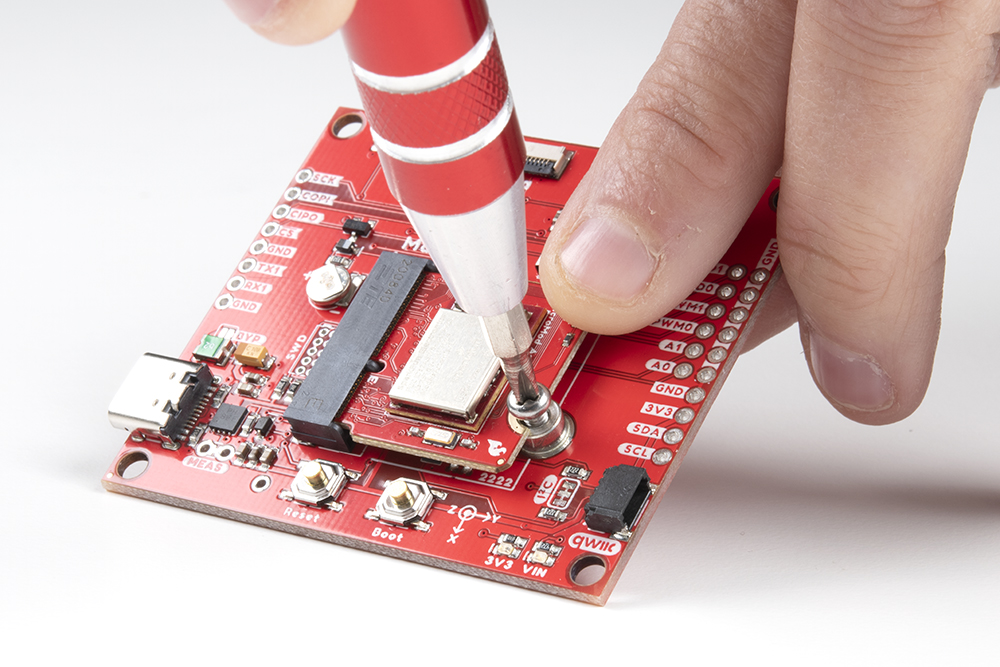
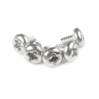
Once the board in the socket, gently hold the MicroMod Processor Board down and tighten the screw with a Phillip's head. We recommend the classic SparkFun reversible mini-screw driver, MicroMod Screwdriver, or the fancier pocket screw driver set but any #00, #0, or #1 Phillip's head driver will work.
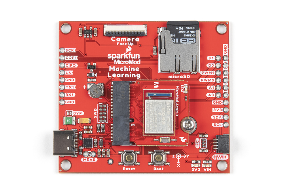
Once the board is secure, your assembled MicroMod system should look similar to the image below!
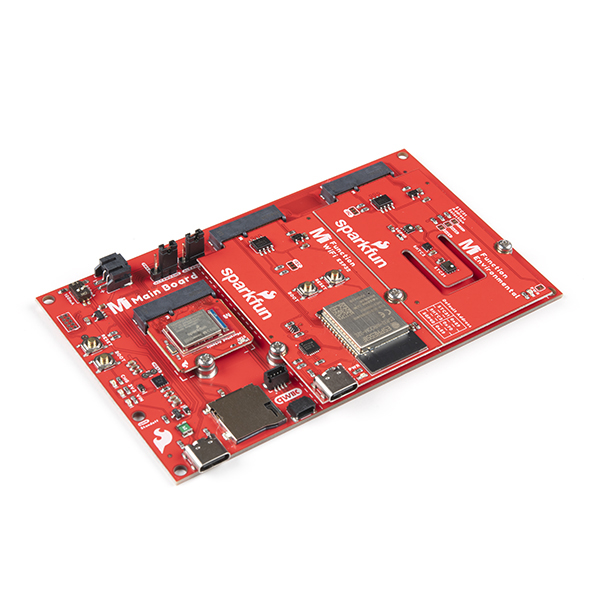
Connecting a Function Board to a Main Board
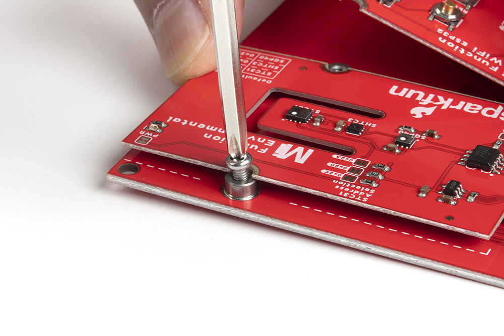
For those going the modular route with a Main Board, you will need a Processor and Function Board. The steps are similar to connecting a processor to a regular carrier board as explained above. Insert a Processor Board into the M.2 connector labeled as "Processor" at an angle of around 25°. Then secure the board using a Phillip's Head. Again, we recommend the classic SparkFun reversible mini-screw driver or the fancier pocket screw driver set but any #00, #0, or #1 Phillip's head driver will work.
 |
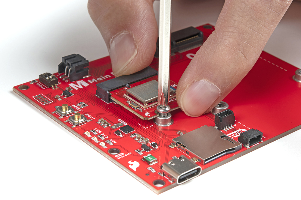 |
| Processor Board Inserted at Angle | Processor Board Being Secured |
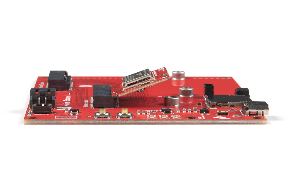
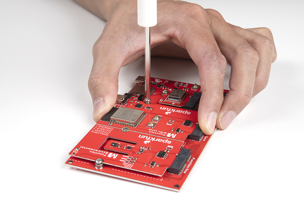
Then insert the Function Board at an angle (at around 25°) to the M.2 Connector labeled as "Function Zero" just like a Processor Board.
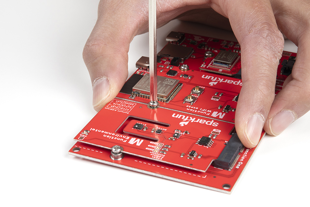
Once the board is in the socket, gently push down the MicroMod Function Board against the Main Board. Hold the Function board against the M.2 connector in place with your index finger and thumb. Then tighten one screw with a Phillip's head just enough to hold it in place. You'll want to avoid tightening the screw fully.

While still holding the Function Board in place, tighten the second screw on the other side to hold it in place. Go back and tighten both screws fully to ensure that the board is evenly held down.

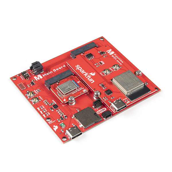
Once the boards are secure, your assembled MicroMod system should look similar to the image below!
If you have a MicroMod Main Board - Double, the steps are the same as the Main Board - Single. The steps are similar to connecting a Processor and Function Board as explained above. Insert both Function Boards at an angle of around 25°.
Gently push down one of the Function Boards against the Main Board - Double. Hold the Function Board against the M.2 connector in place with your index finger and thumb. Then tighten one of the screws (avoid the middle screw between the two Function Boards) with a Phillip's head just enough to hold it in place. You'll want to avoid tightening the screw fully.
Gently push down the other Function Board against the Main Board - Double. Hold the Function Board in place while ensuring both boards are flush. Then tighten one of the screws (avoid the middle screw between the two Function Boards) with a Phillip's head just enough to hold it in place. You'll want to avoid tightening the screw fully
Tighten the middle screw while holding both Function Boards down. Go back and tighten all three screws fully to ensure that the boards is evenly held down.
Once the boards are secure, your assembled MicroMod system should look similar to the image below!
Designing with MicroMod
Can I Make My Own MicroMod Processor Board?
Absolutely. SparkFun is an open source hardware company and is not patenting this interface. All we ask is that you don’t fork the spec, follow the rules, and try not to muddy the community by introducing competing or partially compatible similar interfaces.
We recommend starting from one of our open source processor board designs. Currently all these files are EAGLE PCB format. If you have a different PCB package and you'd like to add your design to the list as a reference design please let us know!
Additionally, we've written Designing with MicroMod that goes into depth about how to create a good processor and carrier board.
Can I Make My Own MicroMod Carrier Board?
Absolutely! This where things get really exciting. We’ve got a variety of resources including a connector footprint and symbol for Eagle PCB. We had multiple carrier boards already designed and open source so you can use them as a reference design and starting point. We can’t wait to see what you make.
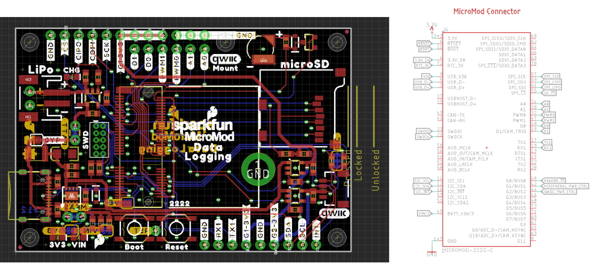
We recommend starting from one of our open source carrier board designs. Currently all these files are EAGLE PCB format. If you have a different PCB package and you'd like to add your design to the list as a reference design please let us know!
- MicroMod All The Pins (ATP) Carrier Board
- MicroMod Data Logging Carrier Board
- MicroMod Machine Learning Carrier Board
- MicroMod Input and Display Carrier Board
Additionally, we've written Designing with MicroMod that goes into depth about how to create a good processor and carrier board.
When designing your own carrier board keep these rules of thumb in mind:
- All carrier boards must provide a regulated 3.3V supply capable of 1A.
- All carrier boards must provide a USB D+/- connection for programming.
- Not all processor boards have connections to every pin.
- The A0/1, PWM0/1, and D0/1 should be supported by every processor board so you can trust that those pins will be available.
- UART1, SPI, and I2C ports are super common and on nearly every processor board, but peripherals beyond those varies between processor boards. For example: support for a 2nd I2C port varies a lot so if your carrier board requires the 2nd I2C port be aware of what processor boards will be supported.
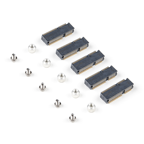
To help get you started with your own custom carrier board we've put together the MicroMod DIY Carrier Kit that includes 5 of the connector, screw, and standoff so that you can get all the ‘special’ parts you may need to make your own carrier board.
The M.2 connector has a 0.5mm pitch and alignment pegs. Hand stenciling and reflow-at-home is possible but we recommend using a stainless steel stencil (do not use mylar) and a higher quality reflow oven (sorry hot plate!) to help prevent jumpers.
Tell Me about Heat Sinking!
One of the benefits to the M.2 standard is the ability to put components under the module. Using this we can now add heatsinks to our microcontrollers!
For this reason we recommend the connector with 4.2mm height. TE makes the 2199230-4 that is widely available and for reasonable cost (1k budgetary pricing is $0.56).
What if I Need A LOT of GPIO?
There are applications where a user will need more than 12 GPIO. The MicroMod specification is flexible. If you would like to design a MicroMod that has only a few peripherals connected (for example, just UART and I2C) and leaving the rest for GPIO (45 available for GPIO in this example) that’s fine. Your carrier board would utilize the UART and I2C pins in the normal location and GPIOs in non-standard locations. This would prevent other MicroMods from being absolutely compatible (perhaps one or two of the MicroMod Artemis would not be able to drive your carrier board’s relays) but it’s allowed. You, the designer, just need to think about the tradeoffs.
We’ve written a guide for creating a MicroMod Processor Board but here are the guiding principles:
- Connect dedicated hardware of the microcontroller to the available I2C, SPI, UART, USB, USB_HOST, CAN, SDIO, and JTAG pins exposed on the MicroMod connector edge.
- Next, A0/A1 on the MicroMod connector edge should be assigned to pins on the microcontroller that are exclusively ADC (no PWM capability).
- PWM0/PWM1 should be assigned to pins that are exclusively PWM (no ADC capability).
- D0/D1 should be assigned to pins that are exclusively GPIO (no ADC or PWM capability)
- Remaining pins should be assigned to Gx with ADC + PWM capable pins given priority (0, 1, 2, etc) positions
- The intent is to guarantee PWM, ADC, and Digital Pin functionality on those specific pins. Whereas Gx pins do not guarantee ADC/PWM function.
- If the microcontroller lacks a specific pin function, and has left over GPIO, they can be over-ruled with GPIO. For example, CTS/RTS can be overwritten with a GPIO if the microcontroller does not have flow control.
For more information, check out the Designing with MicroMod tutorial.
Designing with MicroMod
Resources and Going Further
Valuable MicroMod documents:
- SparkFun MicroMod Interface v1.0 - Pinout
- SparkFun MicroMod Interface v1.0 - Pin Descriptions
- SparkFun Eagle Libraries contains example footprints for the M.2 connector and SMD standoff
- M.2 MicroMod Connector Datasheet
- M2.5 Reflowable Standoff Datasheet
- MicroMod Info Page
- MicroMod Forums
Now that you are familiar with the basics of the MicroMod, check out some of related following tutorials with MicroMod!