Gator:starter ProtoSnap Hookup Guide
 Englandsaurus
 Introduction
The gator:starter is one of a series of gator-clippable boards called gator:boards that SparkFun has created to interface with the micro:bit and gator:bit v2 expansion for micro:bit. The gator:starter is a nice contained package of a temperature sensor, an RGB LED, and light sensor. In this hookup guide we'll go over how to hook up each of the individual boards, along with some examples involving all of the boards together.
SparkFun gator:starter ProtoSnap
SEN-14891Required Materials
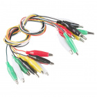
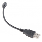
For this activity, you'll of course a micro:bit. You'll also need some alligator clips to connect everything together, and a micro-B USB cable to program your micro:bit. All of these things are shown below, so grab them if you haven't already. The gator:bit v2 is recommended if you'd like to add some more input and output to your micro:bit, but you'll be able to get along fine with just a micro:bit.
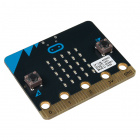
micro:bit Board
DEV-14208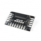
Suggested Reading
If you decide to use the gator:bit v2 and it's your first time using the board, check out the gator:bit v2 Hookup Guide.
SparkFun gator:bit v2 Hookup Guide
Also, if you're starting out with electronics and aren’t familiar with the following concepts, we recommend checking out these tutorials before continuing.
What is a Circuit?
Voltage, Current, Resistance, and Ohm's Law
What is Electricity?
Light-Emitting Diodes (LEDs)
Analog vs. Digital
Getting Started with the micro:bit
Hardware Overview
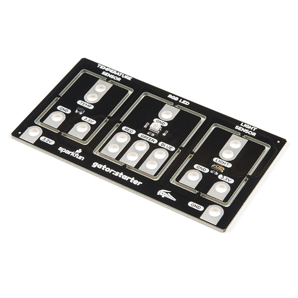
The gator:starter contains 3x boards that can be snapped out of the main assembly simply by twisting back and forth repeatedly. The available boards are:
- temperature sensor (MCP9700)
- common cathode RGB LED
- light sensor (TEMT6000)
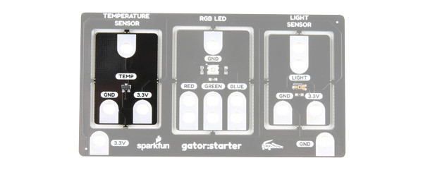
Temperature
The temperature sensor (MCP9700) is an analog sensor. Simply provide power to the sensor on 3.3V and GND. To read, you would connect the TEMP pin to the micro:bit's analog input.
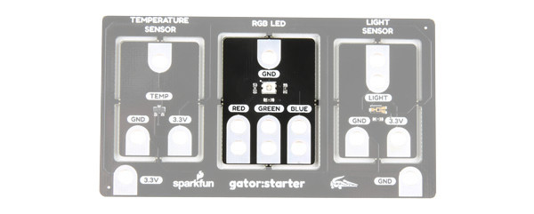
Common Cathode RGB LED
The center component is a common cathode RGB LED. Each individual LED is connect to the GND pin. You would need one I/O pin per color to light up.
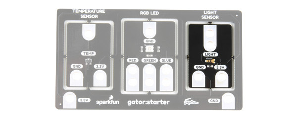
Light Sensor
The light sensor is also an analog sensor. Simply provide power to the sensor on the 3.3V and GND pin. To read, you would connect the LIGHT pin to a micro:bit's analog input.
Power Tabs
We've broken out the power (3.3V and GND) so it can be clipped to on the edge of the board for power without breaking each board away from the main board. These power pins are outlined in the image below.
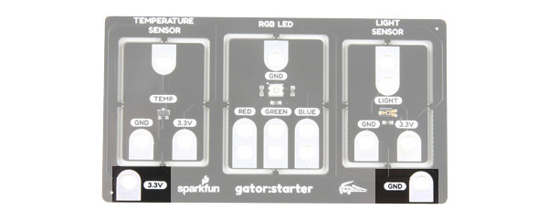
There are also power tabs available on each board if you choose to break the gator:starter into its basic components. Try not to hook power up backwards! If you don't break the board apart however, you'll still be able to interface with all of the sensor and light pins.
Hardware Assembly
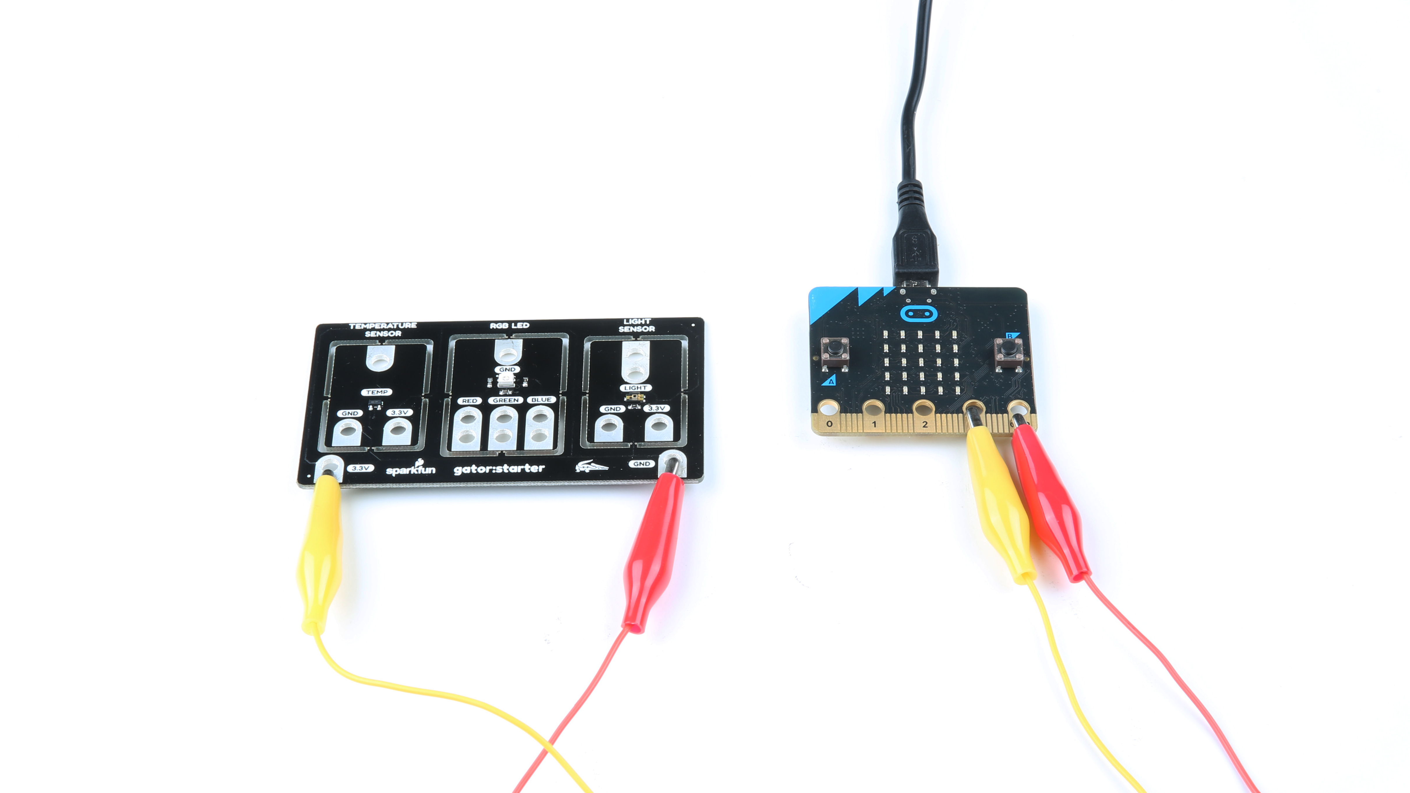
Connecting the gator:starter to the gator:bit v2 is a relatively simple process that doesn't even involve any soldering, all you'll have to do is clip onto the tabs to make your connection. Let's start by powering the gator:starter.
Power
When connecting power there are a few practices you should get used to doing. The first of these is to always connect ground (GND) first. Second, you want to make sure that you aren't powering your device with the wrong voltage, as powering a 3.3V device with 5V could damage the device. Keeping these things in mind, go ahead and clip the ground of your gator:board to ground on the gator:bit. Once this is done, go ahead and do the same with 3.3V. Now that power is connected, we can go ahead and start connecting to our sensors.
Signals
Temperature Sensor
The temperature sensor onboard is an MCP9700 analog temperature sensor with a temperature range of -40°C to 125°C. This sensor outputs an analog signal so you'll need to connect it to a pin on the gator:bit that is capable of reading an analog signal. The analog capable pins are pins 0, 1 and 2. Go ahead and clip the TEMP pin to any of those three pins.
RGB LED
The RGB LED is three LED's (red, green and blue) all combined into a single package. It's a common cathode LED which means that all three of the LED's share the same ground pin. To activate any color, simply make sure ground is connected, then connect 3.3V up to the color you'd like to turn on. Colors can be added and mixed simply by connecting more than one color. If you want to create even more colors, you can connect the LED to any of pins 0, 1 and 2 to allow for things like dimming and full color control.
Light Sensor
The light sensor onboard is a TEMT6000 ambient light sensor. This sensor is also an analog sensor, so once again we'll only be able to use it with pins 0, 1 and 2. To connect this sensor, just clip the LIGHT tab to any of the three analog pins.
Using MakeCode
So you've connected your sensors and LED to the gator:bit v2, but how do we get useful information from these sensors? Luckily, SparkFun has written a few MakeCode extensions to allow the gator:bit to make sense of the values that come in from the MCP9700 temperature sensor and TEMT6000 light Sensor.
Installing the Gatortemp Extension for Microsoft MakeCode
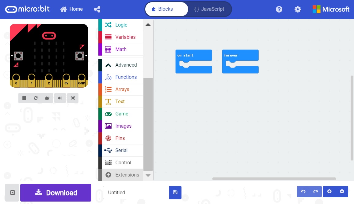
To download the MakeCode extension for the light sensor, go to Advanced -> Add Extensions.
Then search for sparkfun or gator-temp.
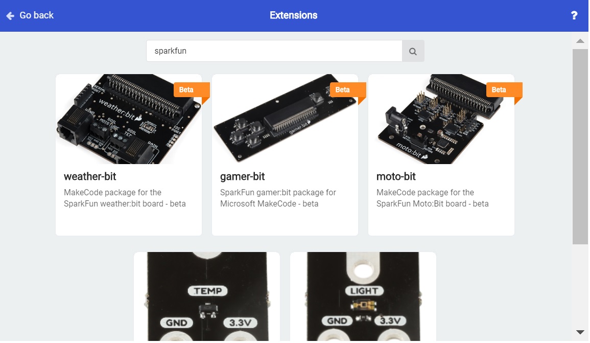
Clicking on the gator-temp will add it to your list of usable extensions in Advanced. Go ahead and open the extension and you'll see a block that allows you to get the temperature on the pin that the gator:temp is connected to.

RGB LED
With the three primary colors, we're able to mix colors to create any color we like. LED's are either on or off, with no brightness in between, so we control brightness by turning the light on and off very fast in a process known as pulse width modulation (PWM). The common cathode LED does not require any additional MakeCode extensions. To use PWM, go to Advanced->Pins and select the analog write block, shown below.
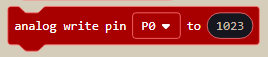
You'll need three of these blocks, one to control each color of the LED. Make sure the pin selected in the block is connected to the proper color (P0 = Red, P1 = Green, P2 = Blue). The analog write block defaults to a value of 1023, or 100%. If you wanted to turn the light down to 50% brightness, you'd plug a value of 511 into your analog write function. This allows for really any color to be created. For instance orange would be created by writing 100% (1023) to red and 10% (102) to green.
Installing the Gatorlight Extension for Microsoft MakeCode
To download the MakeCode extension for the light sensor, go to Advanced -> Add Extension.
Then search for sparkfun or gator-light. Clicking on the gator-light will add it to your list of usable extensions in Advanced.
Go ahead and open the extension to take a look at the variable block we are now able to use. There are two drop down menus that you can use to change which pin the light sensor is attached to as well as the units of the measurement.
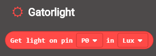
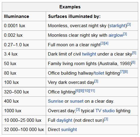
The light sensor measures light in terms of illuminance, or lux. If you're unfamiliar with illuminance, it's basically just a measure of the amount of light reaching a certain spot. The units can either be the raw value from the analog-to-digital converter (ADC) or in units of lux. Check out the chart below to get an idea for what this lux value corresponds to in terms of some common lighting situations.
This block can be used to modify the value of a variable in MakeCode.
Examples
Simple Thermometer
Hardware Hookup
In this example, we'll use Makecode and the gator:temp to create a simple thermometer. The goal is to read the temperature from the sensor, then have the micro:bit display the number as scrolling text. To start, go ahead and power the gator:temp by clipping to the micro:bit, then connect the temp pin to pin 0 on the micro:bit (It's also possible to connect to pins 1 or 2) This will allow the micro:bit to read the analog value on pin 0.
MakeCode
Now we need to program our micro:bit using Makecode to do what we want. In this example, we only need to display the value of the temperature once, so we won't need to create a variable to store the value. In fact, all we'll need to do is use the Show Number block under Basic. What we'll need to do is replace the 0 in the Show Number block with the Get Temperature block in our gator:temp MakeCode extension. This will make the micro:bit read the temperature from pin 0 and show the temperature on the LED screen. Re-create the following code into your MakeCode editor or download the example by clicking the download button to test it out!
Uploading the above code to your micro:bit will result in something like the following gif.
Light Indicator
Hardware Hookup
In this example, we'll go through how to use the gator:light in conjunction with the gator:RGB to create a simple light indicator. Our goal for this example is to create a light indicator to show blue when it's dark, red when it's bright, and shades of purple for everything in between. To begin let's connect all of our components up to one another before we upload code. Begin by powering the gator:temp and connecting the light pin to pin 0. We will then ground the gator:RGB, and connect red and blue to pins 1 and 2, respectively. This will allow the gator:bit to control red and blue on the gator:RGB.
MakeCode
Now let's move on to the Makecode portion, which will tell our micro:bit how to behave. First we need to create a variable to store the value of our light in from the Variables category. Let's call it lightValue for sake of simplicity. Then let's set the lightValue variable to the value that we are reading from our light sensor on pin 0. Use the block in Gatorlight to read the pin P0. Since we're going to be writing this value directly to our LED, we can select units of adcVal from the second dropdown menu. As an ADC (Analog to digital conversion) value has the same range of possible values as the values that we can write to our LED (both range from 0 to 1023). Re-create the following code into your MakeCode editor or download the example by clicking the download button to test it out!
If things are pretty bright outside, the value will be closer to 1023. So you'll end up writing a value that's close to 100% percent brightness to the LED on pin 2 (Blue, if you hooked things up correctly) and a value that's closer to 0 on pin 1 (Red). Moving the light sensor into darkness should give you more red, while bright light should yield blue. Experiment and see how something like a flashlight affects the sensor.
Resources & Going Further
Now that you've successfully got your gator:starter up and running, it's time to incorporate it into your own project! For more information about the board, check out the resources below:
- Schematic (PDF)
- Eagle Files (ZIP)
- About micro:bit Page
- micro:bit Programmer
- GitHub Product Repo
- SFE Product Showcase
Need some inspiration for your next project? Check out some of these related tutorials: