Garmin LIDAR-Lite v4 (Qwiic) Hookup Guide
Introduction
The new Garmin® LIDAR sensor is now easier to use, as a Qwiic device. The Garmin® LIDAR-Lite v4 (Qwiic), fuses the advanced measurement technology of Garmin®'s LIDAR-Lite v4 sensor with the simplicity of SparkFun's Qwiic connect system, for rapid prototyping.
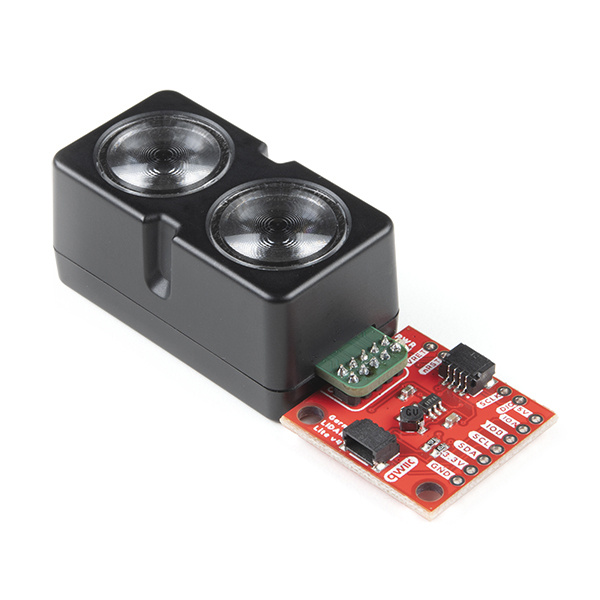
The LIDAR sensor is ideal for drone, robot, IoT, or unmanned vehicle operations, with a range up to 10 meters and 1 cm resolution. Check out the video below for an overview of the product features.
Required Materials
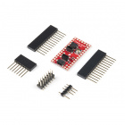
The Qwiic LIDAR-Lite v4 does need a few additional items for you to get started. The RedBoard Qwiic will be used for the Arduino examples. You may already have a few of these items, including the required Qwiic cable, so feel free to modify your cart based on your needs. Additionally, there are also alternative parts options that are available as well (click button below to toggle options).


Qwiic Cable - 50mm
PRT-14426
Qwiic Cable - 100mm
PRT-14427
Qwiic Cable - 200mm
PRT-14428
Qwiic Cable - 500mm
PRT-14429Suggested Reading
If you're unfamiliar with serial terminals, jumper pads, or I2C be sure to checkout some of these foundational tutorials.
Installing an Arduino Library
Installing Arduino IDE
Logic Levels
I2C
Serial Terminal Basics
How to Work with Jumper Pads and PCB Traces
RedBoard Qwiic Hookup Guide
Arduino Shields v2
The Garmin LIDAR-Lite v4 (Qwiic) utilizes the Qwiic connect system. We recommend familiarizing yourself with the Logic Levels and I2C tutorials (above) before using it. Click on the banner above to learn more about our Qwiic products.
Hardware Overview
Board Dimensions
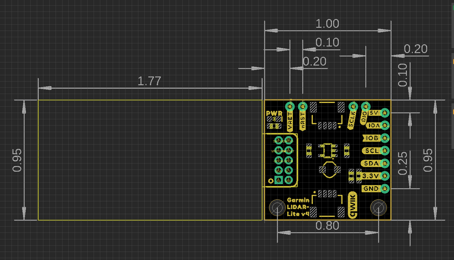
The Garmin LIDAR-Lite v4 (Qwiic) has an attached 1" x 1" Qwiic board for ease of use. The overall product dimensions are approximately 2.8" x 1.0" x 0.9" (L x W x H), with more detailed measurements in the drawing below.
Mounting Options
The Garmin LIDAR-Lite v4 operation manual lists zipties and double-sided tape as attachment methods. There are notches on the sensor housing that appear to be meant for a ziptie.
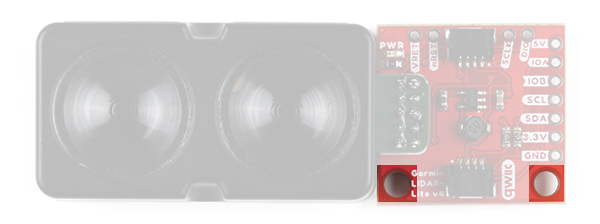
With our Qwiic version, we provide two screw holes on the Qwiic board as an additional mounting option. The holes are compatible with 4-40 screws and hardware.
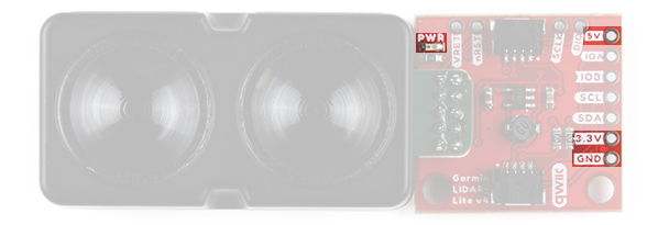
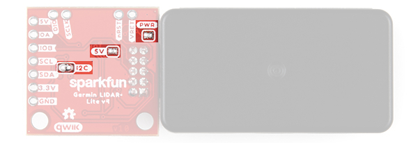
Power
There is a power status LED to indicate when the Garmin LIDAR-Lite v4 (Qwiic) sensor is powered. Power the board either through the polarized Qwiic connector system or the breakout pins (3.3V or 5V and GND) provided. The Qwiic system is meant to run on 3.3V, be sure that you are NOT using another voltage when using the Qwiic system. A jumper is available on the back of the board to remove power to the LED for low-power applications (see Jumpers section below).
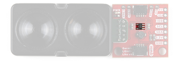
DC-DC Converter
The Garmin LIDAR-Lite v4 sensor requires 5V to operate. In order to provide 5V to the sensor from the 3.3V line of the Qwiic connector, a DC-to-DC voltage converter is utilized. This can also be referred to as the buck/boost converter/circuit. For more details, check out the XC9140 datasheet.
Garmin LIDAR-Lite v4
The Garmin® LIDAR-Lite v4 is a distance measurement sensor. For more details on the sensor, please refer to the operation manual and technical specifications.
Sensor Characteristics
The power and current consumption characteristics listed below are from the operation manual and technical specifications. However, these specifications are for the sensor itself.
To prevent brown outs, users should be wary when attaching several Qwiic LIDAR-Lite v4s to the Qwiic connect system. Users can easily surpass the current (supply) limitation of their Qwiic microcontroller board. The Qwiic LIDAR-Lite v4 operates at 3.3V and we have measured the current consumption from the 3.3V line to be approximately:
- 120mA (idle)
- 165mA (during an acquisition)
Below, are the LIDAR sensor's electrical and performance characteristics, as listed in the operation manual and technical specifications datasheet.
| Characteristic | Description |
|---|---|
| Power (operating voltage) | 4.75 to 5.25 Vdc | Current Consumption |
2 mA idle
85 mA during an acquisition |
I/O Voltage | 3.3 V | Max Range | 5 cm to 10 m (1.97 in. to 32.8 ft.) | Resolution | 1 cm (0.4 in.) | Beam divergence | 4.77 degrees | LED Wavelength | 940 nm | Optical Aperture | 14.9 mm | Measurement Repeatability* |
± 1 cm up to 2 m ± 2 cm up to 4 m ± 5 cm up to 10m |
| I2C Address |
0x62 (Default)
Software configurable |
*NOTE: As measured indoors to a 90% reflective target; 1 cm is equivalent to 1 standard deviation. Measurements were obtained using high accuracy mode.
Qwiic and I2C
I2C Address
The Garmin LIDAR-Lite v4 (Qwiic)’s I2C address, 0x62 (7-bit), is factory set. However, this address is software configurable.
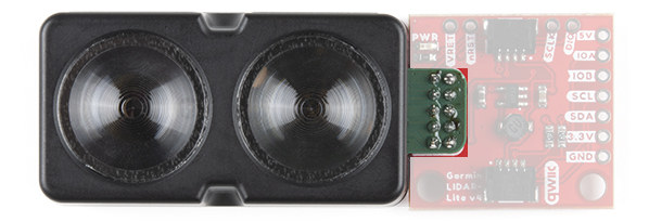
Qwiic Connectors
The simplest way to use the Garmin LIDAR-Lite v4 (Qwiic) is through the Qwiic connect system. The connectors are polarized for the I2C connection and power. (*They are tied to the corresponding power and I2C breakout pins.)
Breakout Pins
5V pin, the rest are 3.3V pins.The board also provides eleven labeled breakout pins. Besides the 5V (and GND) pin, the rest of the pins are only 3.3V tolerant.
I2C
You can connect these lines to the I2C bus of your microcontroller and power pins (3.3V and GND), if it doesn't have a Qwiic connector. The interrupt pins are also broken out to use for triggered events.
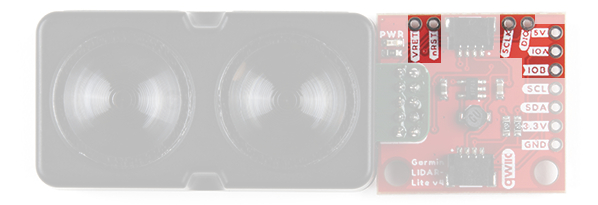
J-Link Debug and I/O Pins
Reprogramming the nRF52840 System on Chip (SoC) removes all pre-programmed factory software. SparkFun is NOT able to help you recover the software once it has been removed.
Before attempting to mess with the the nRF52840 System on Chip (SoC), we highly recommend users refer to the operation manual and technical specifications for other considerations and notices from the manufacturer.
The J-Link and I/O pins are also broken out for users, in case they wish to interface with the RF52840 SoC.
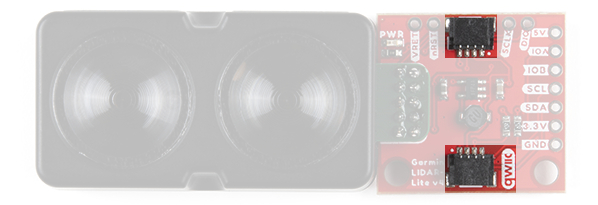
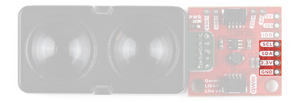
Jumpers
There are three jumpers on the board. Not sure how to cut or modify a jumper? Read here!
- Power LED - Cutting the
LEDjumper will remove the 1kΩ resistors andPWRLED from the 3.3V power. This is useful for lowering power consumption. - I2C Pull-Up - Cutting the
I2Cjumper will remove the 4.7kΩ pull-up resistors from the I2C bus. If you have many devices on your I2C bus you may want to remove these jumpers. - 5V Disconnect - Cutting the
5Vjumper on the board will disconnect the buck converter from the 5V power trace. This is useful when users power the board through the 5V breakout pin.
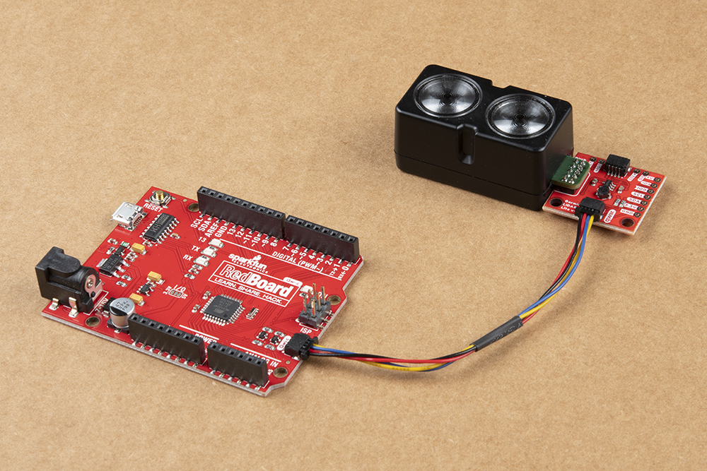
Hardware Assembly
With the Qwiic connector system, assembling the hardware is simple. All you need to do is connect your Garmin LIDAR-Lite v4 (Qwiic) to the RedBoard Qwiic with a Qwiic cable. Otherwise, you can use the I2C pins of your microcontroller; just be aware of logic levels.
Arduino Library
Note: This example assumes you are using the latest version of the Arduino IDE on your desktop. If this is your first time using Arduino, please review our tutorial on installing the Arduino IDE. If you have not previously installed an Arduino library, please check out our installation guide.
We've written a library to easily get setup and take readings from the Garmin LIDAR-Lite v4 (Qwiic). However, before we jump into retrieving measurements from the sensor, let's take a closer look at the available functions in the library. You can install this library through the Arduino Library Manager. Search for SparkFun Garmin LIDAR-Lite v4 Arduino Library and you should be able to install the latest version. If you prefer manually downloading the libraries from the GitHub repository, you can grab them here:
Note: Users may also notice another Arduino for the Garmin LIDAR-Lite. This library is provided and maintained by Garmin®, for all their LIDAR sensors. For more details, check out the GitHub repository.
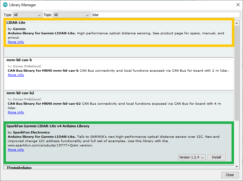
Garmin and SparkFun Arduino libraries for the Garmin LIDAR-Lite v4. (click to enlarge)
Arduino Examples
Example 1: Basic Readings
Once you've got the library installed, open the Example1_GetDistance sketch. You can find it under
File > Examples > SparkFun Garmin LIDAR-Lite v4 Arduino Library > Examples
Then upload the sketch onto your RedBoard or Uno and open your favorite Serial Terminal to see the printed values. (Don't forget to set the baud rate to 115200bps.)

Example 2: Address Change
Open the Example2_ChangeI2CAddress sketch from the library examples.
Once the sketch has been uploaded, open up a Serial Terminal with the baud rate set at 115200bps. There, users will be prompted to input a value to change the I2C address.
Following the address change, the sketch will scan the I2C bus for connected devices and display their address. Users should see the LIDAR sensor at the address they specified.
Troubleshooting
Below, we have also included some troubleshooting tips for issues that you may come across.
- One of our employees compiled a great list of troubleshooting tips based on the most common customer issues. This is the perfect place to start.
- For any Arduino IDE specific issues, we recommend starting with their troubleshooting guide.
If you need technical assistance and more information on a product that is not working as you expected, we recommend heading on over to the SparkFun Technical Assistance page for some initial troubleshooting.
If you can't find what you need there, you'll need a Forum Account to search product forums and post questions.
Resources and Going Further
- Schematic (PDF)
- Eagle Files (ZIP)
- Board Dimensions (PDF)
- Garmin LIDAR Lite v4 Product Information:
- SparkFun: Qwiic LIDAR Lite v4 Arduino library
- Hardware GitHub Repository
- Product Showcase Video
Looking for other distance sensors? Check out some of these tutorials: