Fuse Breakout Board Hookup Guide
Introduction
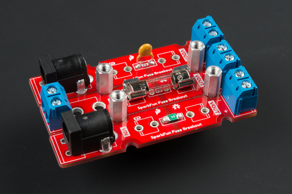
In this tutorial, we will explore two types of fuses, assemble the fuse breakout board, and add it to a circuit for protection!
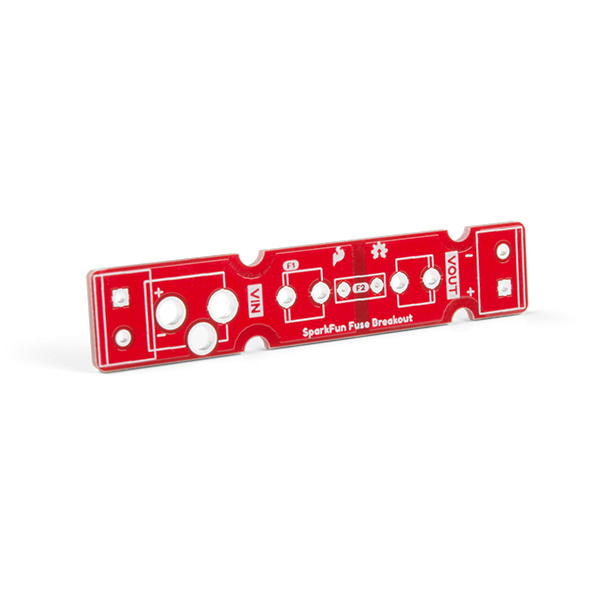
SparkFun Fuse Breakout Board
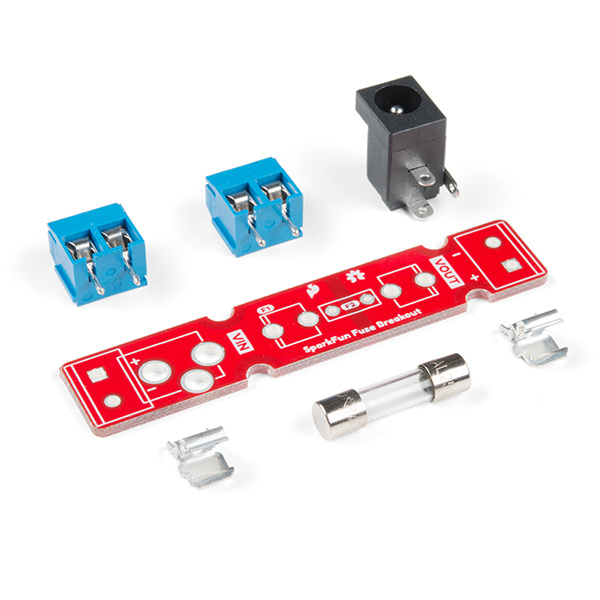
BOB-15697SparkFun Fuse Breakout Kit
KIT-15702Required Materials
To follow along with this tutorial, you will need a fuse with the breakout board! You may not need everything though depending on what you have. Add it to your cart, read through the guide, and adjust the cart as necessary. The minimum components needed for the glass ferrule fuse is included in the kit version. However, we suggest getting more than one glass fuse to replace when prototyping and testing.
SparkFun Fuse Breakout Kit
KIT-15702If you are ordering the breakout board individually, you can pick a fuse that fits your project from our fuse category. Just make sure to get the necessary fuse clips and connectors for your needs.
Fuse 5mm 250V 200mA
COM-10165Fuse 5mm 250V 500mA
COM-10166Tools
You will need a soldering iron, solder, and general soldering accessories.
Suggested Reading
If you aren’t familiar with the following concepts, we recommend checking out these tutorials before continuing.
Connector Basics
What is a Circuit?
Electric Power
Polarity
How Does a Fuse Work?
Fuses are electrical components that help protect your project from overcurrent protection. Depending on the manufacturer and application, there are different current and voltage ratings. The rate at which the fuse blows out can also vary from slow-blow (a.k.a. time-delay), normal-blow, fast-blow, and ultra-fast. There are many types of fuses but we'll be focusing on the following.
- glass ferrule fuse
- resettable fuse (a.k.a positive temperature coefficient or PTC)
Glass Ferrule Fuses
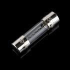
A glass ferrule fuse is usually what comes to mind when you think of a fuse. They're pretty simple. If current exceeds the rating of the fuse, the small filament inside the fuse heats up and breaks (like a light bulb burning out). The circuit is then broken and hopefully your circuit is saved from molten destruction. The glass cartridges are useful for inspecting whether a fuse is blown but they operate a lower current faults compared to ceramic cartridges.
Depending on the specification, you may notice the filament glow and blow out in fiery glory. Or you may notice the filament may just glow for a little bit and melt. In other cases, the filament may bend before disconnecting or melt into tiny, metal spheres (not as exciting).
Resettable Fuses (a.k.a. PTC)
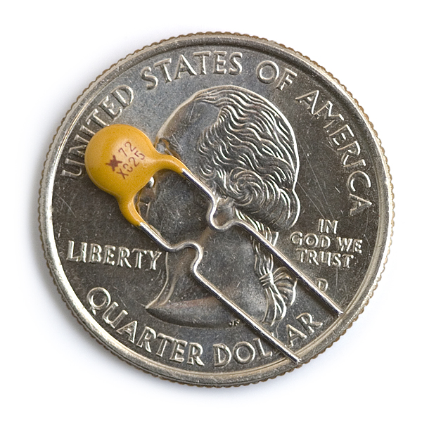
A positive temperature coefficient (PTC) (a.k.a. multifuse, polyfuse, polyswitch, or thermistor) is a device that will increase in resistance as current flows through it. The PTC on the left is for through hole pads while the PTC on the right is for SMD.
 |
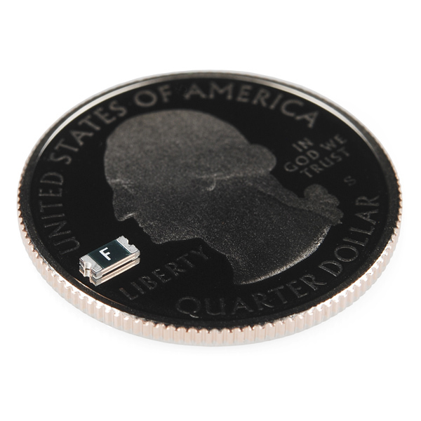 |
| PTH PTC | SMD PTC |
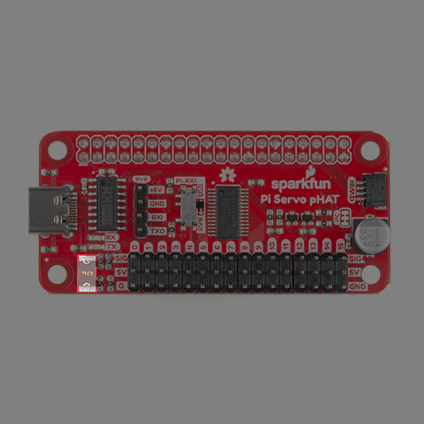
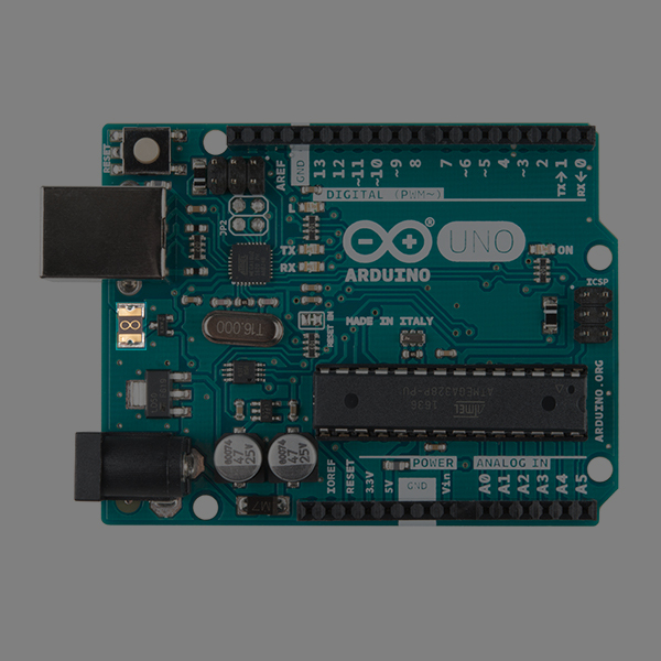
PTCs are your friend! Beginners in electronics will often create shorts or accidentally hook things up backwards. These PTCs can be designed so that at a certain current flow (let's say a 250mA PTC with current protection of 500mA), the resistance increases dramatically, thus limiting the current flow. You can find some of these resettable fuse on certain motor boards and micrcontrollers that connect to a USB port as shown in the following images.
 |
 |
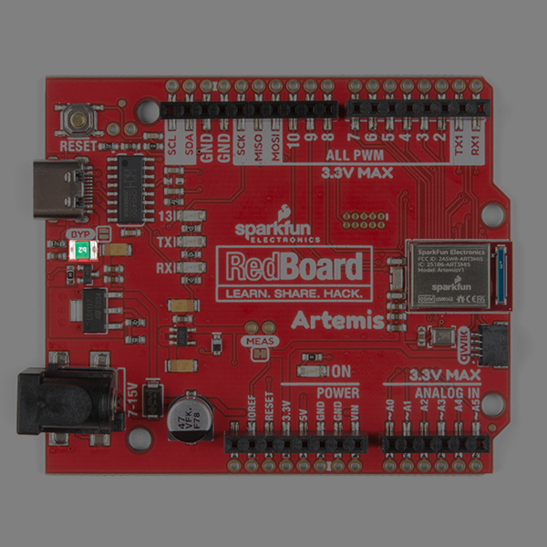 |
| Resettable Fuse on the Servo Hat for a Raspberry Pi | Custom Resettable Fuse for the Arduino Uno | Resettable Fuse for the RedBoard Artemis |
Basically, the PTC acts as a resettable fuse! You will want to place this device in series, before your voltage regulator. If your circuit draws more than 500mA (if you short power to ground for instance), the 250mA PTC will heat up and limit the current to 250mA. Once you remove the short, the current will drop back down, the PTC will cool off and the circuit will start operating normally again. It's a very cool little component that can save many designs from smoking.
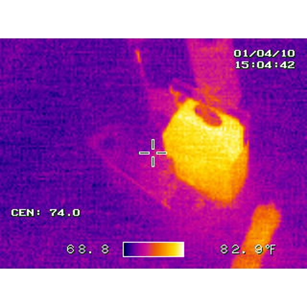
The thermal images below of the PTC through hole fuse do a great job of showing what happens when a PTC is tripped. The thermal picture on the left shows a voltage regulating circuit in its normal state. The picture on the right shows a circuit when it is shorted. Notice how hot the PTC gets (213 °F!) as it limits the amount of damaging current going through the circuit. Major thanks to Joshua Weaver for the great thermal shots!
 |
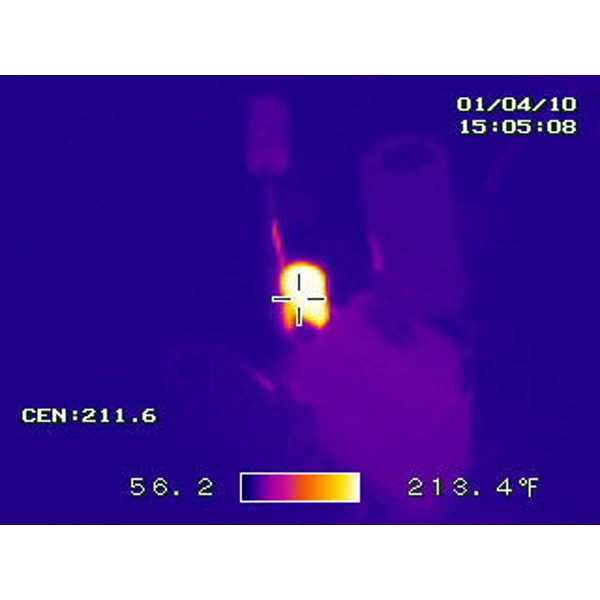 |
| Voltage Regulator Operating Under Normal Conditions | PTC Fuse Tripped Preventing The Circuit from Being Damaged |
Hardware Overview
VIN
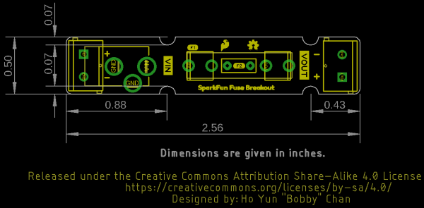
On the left side, we have our input VIN. You can solder 2-pin screw terminal (5mm) on the input side (highlighted in yellow). Or you can solder a barrel jack for the input (highlighted in black) if you decide that you want to easily connect a wall adapter (with a center positive barrel jack) for a polarized connection.
Keep in mind that the 5mm screw terminal is rated for more current compared to the barrel jack contacts. However, DC wall adapters sold from the catalog use barrel jacks to provide power. You can also solder wires directly to the breakout board as long as they are rated appropriately for the project.
Glass Fuse
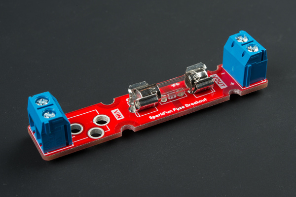
The fuse breakout board has been tested up to a 5A glass ferrule fuse.
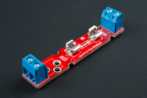
There are two clips that will need to be soldered to the board if you are using a glass cartridge fuse. Make sure to solder the clips correctly.
PTC Fuse
Through holes for a PTC fuse was added in case you decided to use a resettable PTC fuse. While the board was designed for a through hole PTC, you can solder still solder a SMD PTC fuse to the pads when prototyping. The component just may not fit as snug depending on the size of the SMD fuse.
VOUT
On the right side, we have our output VOUT. You can solder a 2-pin screw terminal (5mm) here.
Mounting Holes
There are four mounting holes on the board if you decide to mount the board to a panel or in an enclosure. To ensure that the board size is reduced to a minimum, half of a mounting hole was included.
Board Dimensions
The board is 0.50in x 2.56in. There are four semi-circle mounting holes should you decide to mount the board or place them side by side.
Hardware Assembly
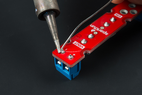
You'll need to solder your connectors and fuse clip to the breakout. You can solder the components in any order that you would like. If you have not soldered before, check out our tutorial below for tips!
How to Solder: Through-Hole Soldering
Solder Input and Output Connectors
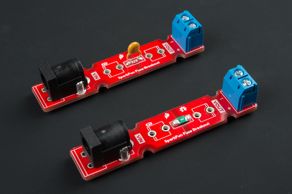
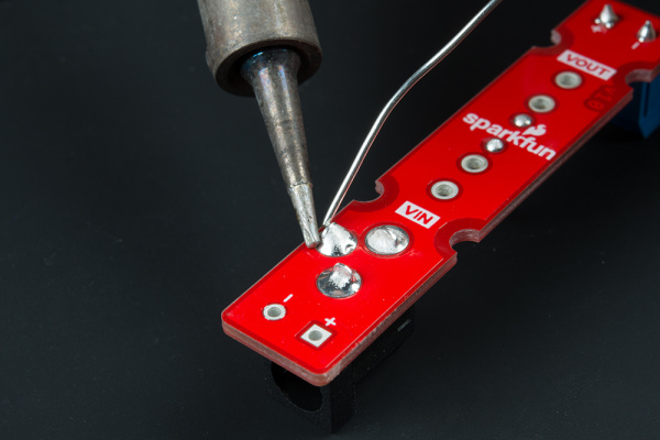
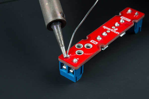
On the VIN side, you have two options. For those that are using this with wall adapters with a center positive barrel jack, you'll want to use it with a barrel jack connector. Otherwise, you can solder 5mm screw terminal on the VIN side.
 |
 |
| Barrel Jack for VIN | 5mm Screw Terminal for VIN |
Once you have the input soldered, add the screw terminal to the VOUT side.
Solder 5mm Fuse Clips
The next step is to solder the glass fuse's clips to the board. Insert the clips to the each side. You'll need to make sure that the clips are oriented correctly before tacking each leg down to the board. If you look closely at the silkscreen for each fuse clip, you will see one side of the square has a secondary line added. This is the side you should orient the curved bits towards. Once each leg is tacked down, solder the other leg down. The clips can get hot when soldering so you may want to tape it down against the board or use a small piece of cardboard to hold the clip against the board.
Adding a Fuse to Your System
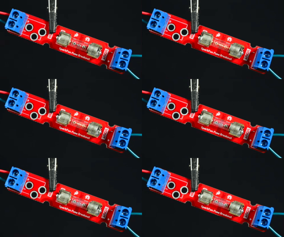
If you are using a glass fuse, you can now insert the glass cartridge into the clips. Should your fuse blow out, just grab a flat head screw driver and carefully pry it out.
Otherwise, insert a barrel jack into VIN side or tighten the screws to hold down stripped wires between your power supply and load. Make sure to take note of the silkscreen for your voltage and ground wires.
Mounting
Part of the design includes semi-circle mounting holes. This is useful if you decide mount the board to a panel or enclosure. To mount, you will need to:
- tighten some standoffs (or a screw and standoff)
- ensure that there is room to slide the PCB(s) between the hardware
- place the PCB between your standoffs to tighten
- if you are using more than one fuse breakout, place the standoffs between the two PCBs before tightening
- repeat for each standoff
Considerations When Choosing a Fuse
Choosing a fuse depends on your project. Here are a few considerations when placing a fuse after your power supply or battery.
Project Voltage & Current Requirements
You'll first want a fuse that is able to handle your load's voltage and current. The datasheet for the fuse should provide that information. Then measure the maximum power that the project is expected to pull from your power supply without damaging the circuit. If the project is outputting an excessive amount of heat for a period of time, you may want to take that into account. With the measurements, you'll want to decide the current at which the fuse blows or trips. This value is usually at or below the trip current and within the power suppliy's amperage (i.e. if you want the fuse to trip when part of your load pulls 1A with a 20A high current power supply). Projects that have brief spikes in current (such as robots using motors) would need a slow blow (a.k.a. time-delay). Other projects may require the fuse to be blown out immediately would require a fast or ultrafast. We'll assume that they will be used at room temperature.
Glass Ferrule Fuse or PTC
For high current power supplies, you may want to consider using a glass ferrule fuses that disconnects and blow out in your project. For lower current power supplies, you may want to consider using a resettable fuse. Just keep in mind that the resettable fuses can get hot when tripped and can still leak current to your load.
Stress Testing
Once you have decided on a fuse to use for your prototyping needs, make sure to test it out! Yes, that means sacrificing your glass ferrule fuse but you'll want to ensure that the component works as expected when your circuit starts having a mind of its own.
Example
High Current Power Supplies
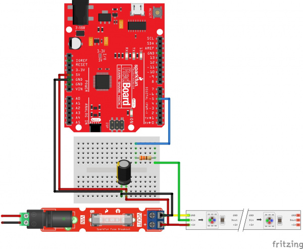
The inspiration for designing this board came after reading Hackaday's article: The Engineering Case for Fusing Your LED Strips. For power supplies with high current output, they'll simply keep pouring current to your load. This can damage your circuit and present quite a fire hazard. Placing the fuse close to your power suppliy's output can protect your circuit in case anything happens down the line. In this case, we'd want the fuse to blow out and disconnect the power to the rest of the LEDs. If you are using multiple LED strips off of one high current power supply, you would simply divide the current for each LED strip section.
Low Current Power Supplies
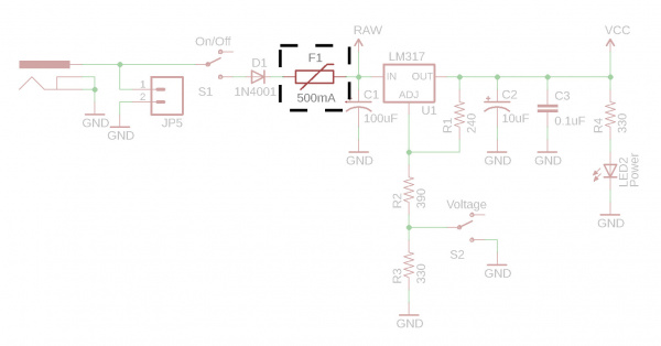
If you decide to use a resettable PTC fuse with low current power supply, you could place it right after your input voltage. Below is an example schematic with the PTC placed between the wall adapter and voltage regulator. Placing a PTC fuse with the breakout board when prototyping is useful if you need to quickly test the setup before including it in the final design.
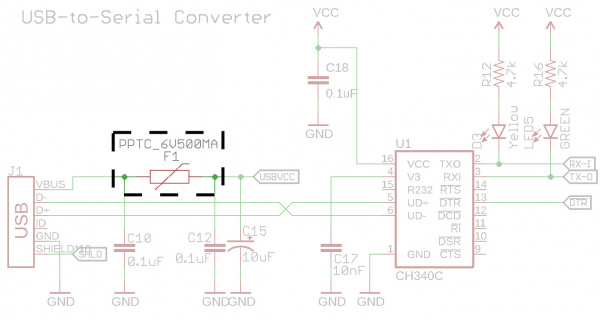
Below is an example of placing a PTC fuse between the USB connector and microcontroller.
Resources and Going Further
Now that you've successfully got your fuse breakout board up and running, it's time to incorporate it into your own project! For more information, check out the following links.
Need some inspiration? Check out some of these other related tutorials:
Benchtop Power Board Kit Hookup Guide
Beefcake Relay Control Hookup Guide
12V/5V Power Supply Hookup Guide
Current Sensor Breakout (ACS723) Hookup Guide
Breadboard Power Supply Kit 5V/3.3V Quickstart Guide
Or check out the following blog posts for ideas:
