Force Sensitive Resistor Hookup Guide
 jimblom,
  bboyho
 Hardware Assembly
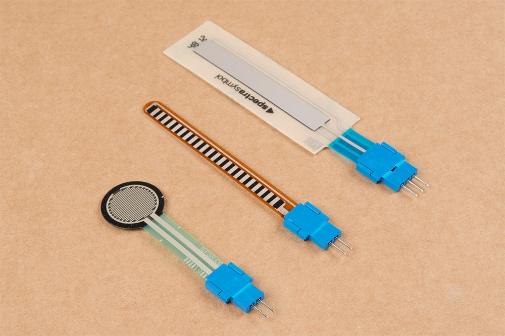
The sensors have solder tabs that are stapled through a flexible substrate to make contact with the semi-conductive material. Depending on your project application and skill set, there are a few methods of connecting to the sensor. Some assembly may be required to connect to the pins reliably.
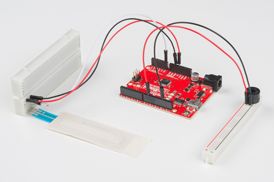
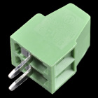
Breadboard Compatible Tabs
For prototyping and testing, these solder tabs can be inserted into a breadboard or female jumper wires. Here are two examples with the flex and soft potentiometer sensors.
 |
 |
| Flex Sensor Inserted Vertically on Breadboard with Space to Bend | SoftPot Inserted Vertically on Breadboard Flush Against the Table |
Soldering to Tabs
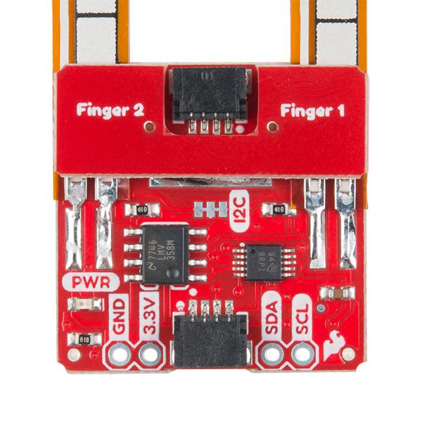
When integrating it into a long term project and installation, there is an option to solder wires or a PCB directly to the solder tabs. However, excessive heat can melt the material and damage the sensor due to the limitations in the flexible substrate and the semi-conductive material. Below is an example of the flex sensor soldered to a PCB from our production assembly technicians.
While the datasheet states that you can solder to the force sensitive resistor's solder tabs, we only recommended for advanced users that have experience with soldering. For those soldering to the force sensitive resistor, you would need to solder at a lower temperature and ensure that the soldering iron is not heating the tab for no more than 1 second. Any longer and you can damage the material and semi-conductive material. The force sensitive resistor in particular is more susceptible to damage compared to the flex sensors and SoftPot.
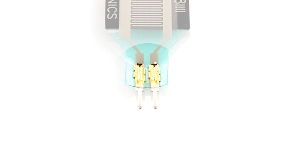
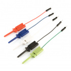
Amphenol CFI Clincher Connector
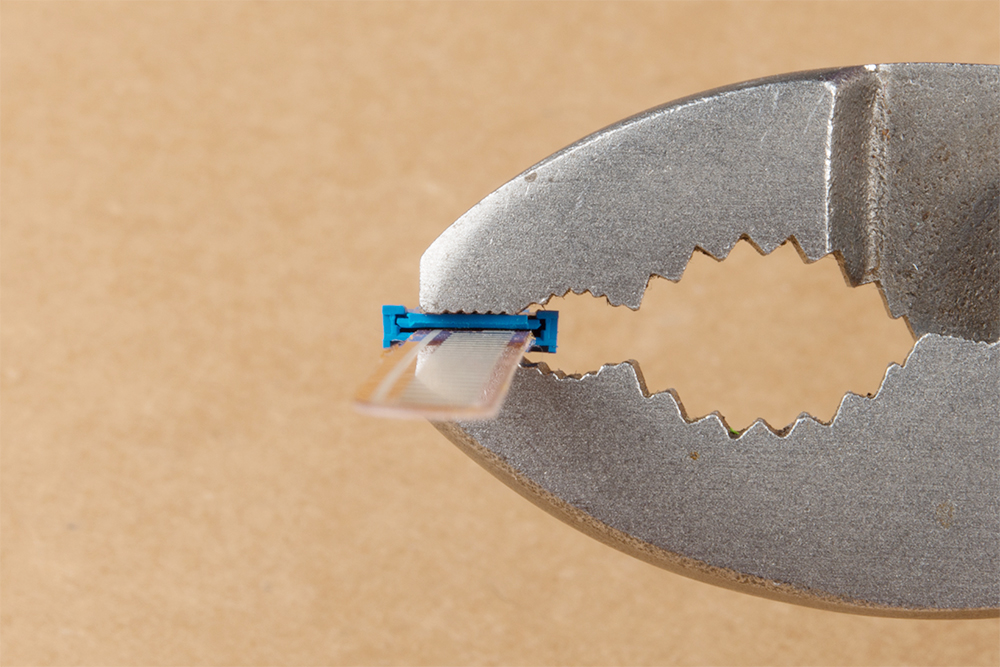
As an alternative, users can use the Amphenol FCI Clincher connector to make a reliable connection to the sensor and provide a small amount of strain relief on the crimped connector. This is recommended for those that have not soldered before and are using the sensors in an long term projects beyond the breadboard or in a classroom setting. The connector was designed to crimp pins on flexible printed circuits as an alternative to applying heat to heat sensitive components such as the semi-conductive material or conductive ink.
Crimping the Clincher Connector
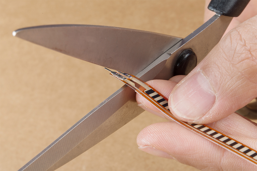
We'll be using the male Clincher connector to crimp down on the flex sensor. However, the instructions listed below can be applied to the force sensitive resistor as well.
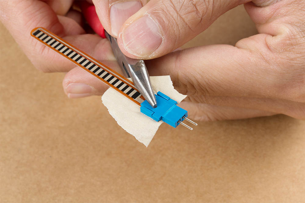
To connect, you will need to cut off the solder tabs on the sensor. Make sure to cut as close to the solder tabs as possible. You can have issues connecting to the semi-conductive material if you cut off too much of the sensor. The length of the semi-conductive pads on the SoftPot is smaller than the force sensitive resistor and flex sensor.
 |
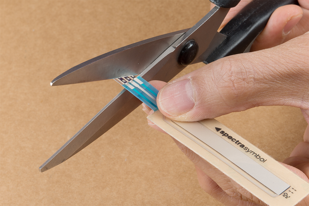 |
| Cutting Solder Tabs Off Flex Sensor | Cutting Solder Tabs Off Slide Pot |
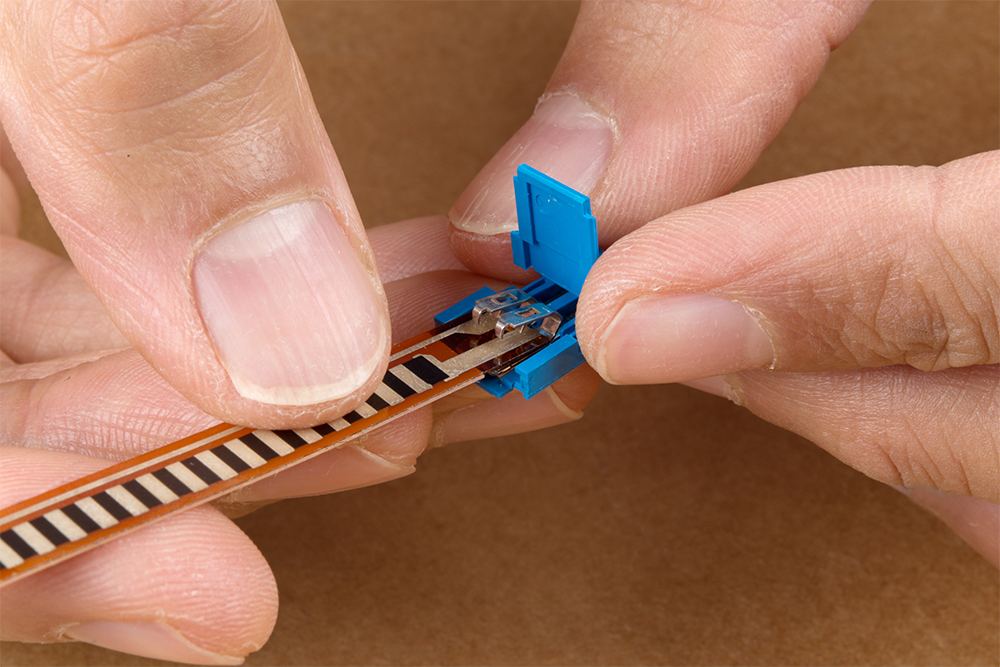
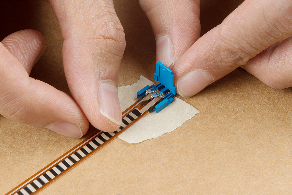
After cutting the staples off, insert the sensor in the respective Clincher connector. Make sure to align the semi-conductive material with the new staples or you may create a short. Depending on the sensor, you may have less semi-conductive material to work with. The SoftPot will have smaller pads to work with after cutting the solder tabs off as shown on the image to the right.
 |
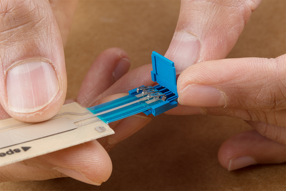 |
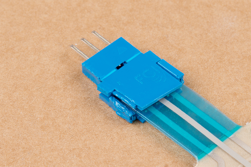
| Inserting the Flex Sensor into the 2-Pin Clincher Connector | Inserting the SoftPot Sensor into the 3-Pin Clincher Connector |
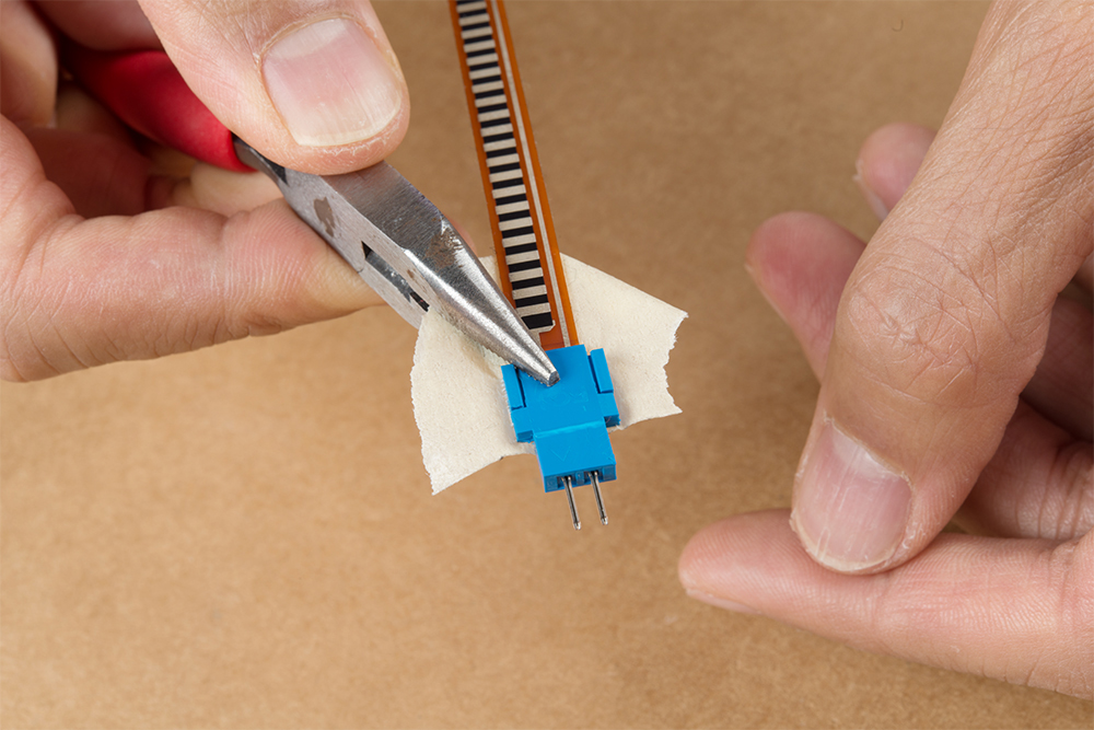
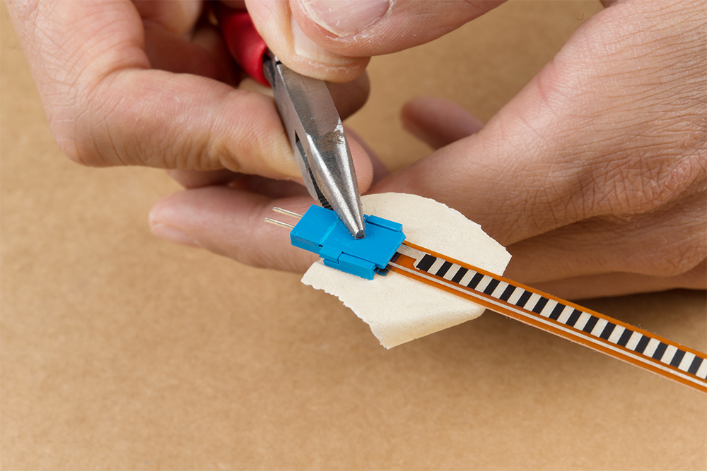
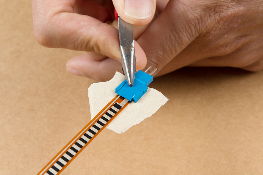
Once you have aligned the sensor, we recommend adding a piece of tape to hold down the sensor with the Clincher connector to prevent the sensor from moving around when clamping the connector down.
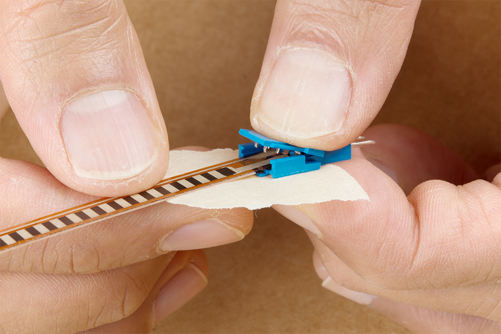
We recommend using a flush, slip joint plier to clamp the connector down. As you can see from the image, the force is being applied on the center of the latch and staples instead of along the grooves on the side of the connector. The force sensitive resistor will be easier to clamp down compared to the other flexible substrates on the flex sensor and SoftPot. You will hear a small but satisfying pop when the crimp pins bite through the sensor.
Otherwise, needle nose pliers can be used to clamp the staples to the sensor. Close the tab to hold the crimp pins against the semi-conductive material. Then make sure to carefully apply force on the center from each corner (while avoiding the grooves on the side).
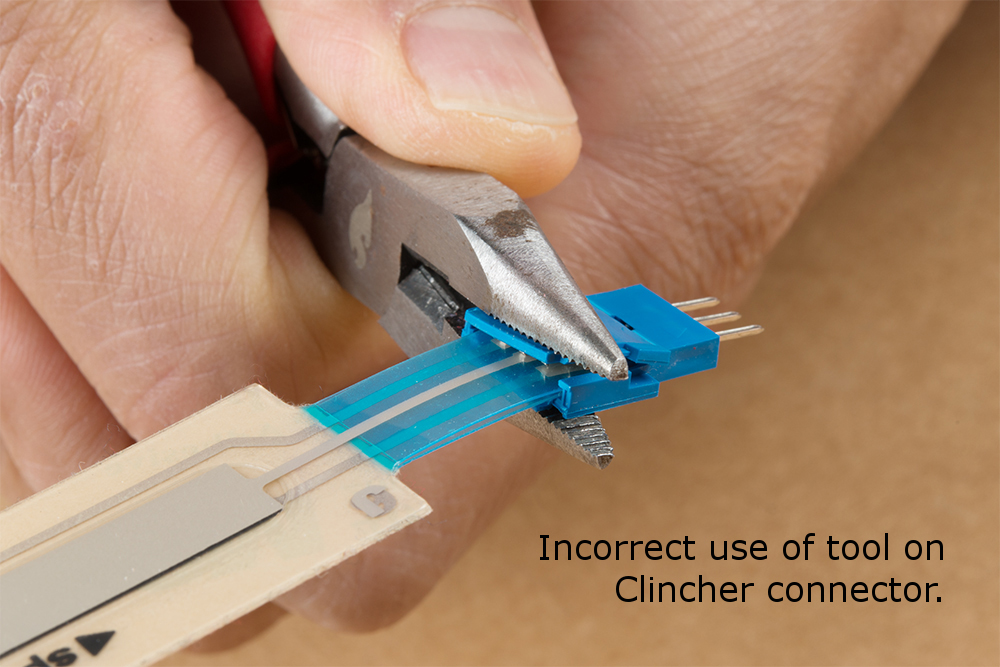
If you apply force incorrectly with needle nose pliers, there is a risk of damaging the plastic housing. The image on the right shows the Clincher connector housing damaged even though the crimp pins are making contact with the SoftPot.
 |
 |
| Pliers applied incorrectly to the Clincher connector. | Clincher connector's housing damaged for the SoftPot. |
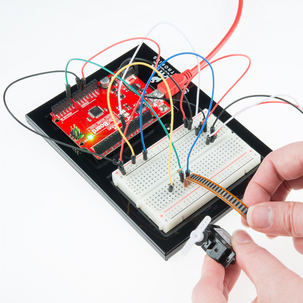
When finished, remove the tape from the back. To test, you can use a multimeter to determine if the sensor has a short or is able change in resistance. You can also connect the sensor to your circuit using jumper wires to check if the sensor is working as expected.