Electric Imp Breakout Hookup Guide
Hardware Hookup
The hardware hookup approach in this guide is just one of many ways to use the board. The breakout is made to be a versatile extension of the imp. You can connect whatever you want to the imp pins, and power the board however your project requires.
Solder Headers
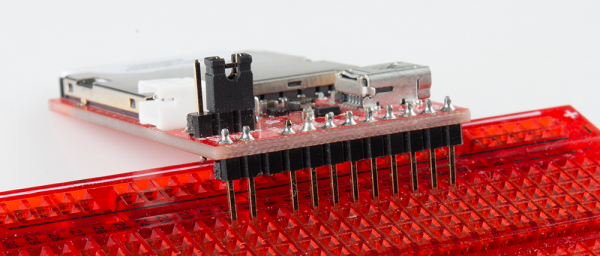
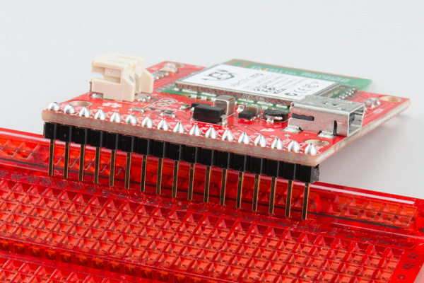
In order to do much with the input/output capability of the imp, you'll need to solder to the broken out pins. If you want to use the imp Breakout with a breadboard or perfboard, 0.1" male headers make for a good choice. Depending on your application, you could swap the headers with wire, female headers, screw terminals, or a variety of other connectors.
We're going to solder male headers into the board, so we can use it with a breadboard later on.
Apply Power
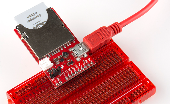
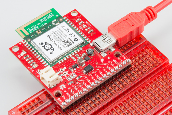
Depending on what you want to use for your power source there are a few options here. You could use the on-board USB connector. Or you could solder down a 2-pin JST connector, and plug battery (LiPo or AA) into the board to make it mobile. If you go with either of those options on the imp card Breakout, you'll also need to set the jumper (the imp002 Breakout will automatically select the higher voltage).
Alternatively, you can apply power straight to the headers labeled "VIN" and "GND". This pin bypasses the jumper and goes straight to the regulator.
Plug in the imp!
If you have the original imp card, plug the imp card in so the suspicious little imp logo is facing up. If you've got power to the board, once plugged in, the imp should start blinking orange. If there's no blinking on the card, it's probably not getting any power. Double-check that the jumper is set correctly.
If you have the imp002, the status LED should start blinking orange as soon as you apply power.
What's all that blinking signify? How do we get the imp connected to our wireless network? Read on!


