E-Textiles ISTE Workshop
 Gella
Gella 
Going Further: RGB LED
In this activity we'll control a colorful LED!
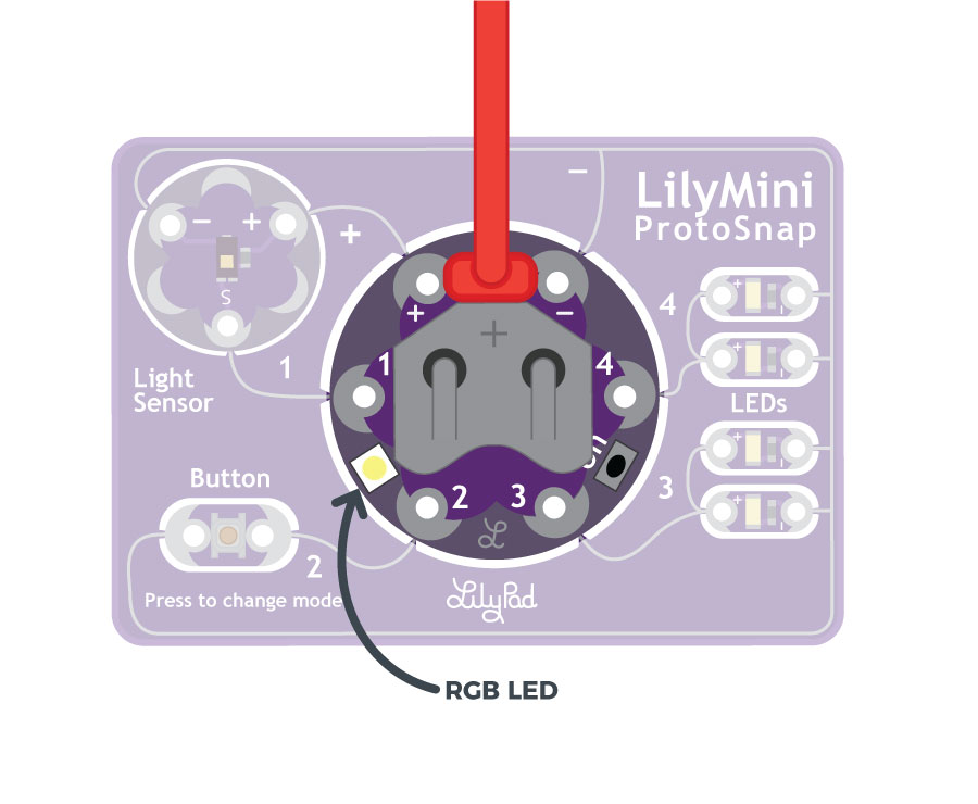
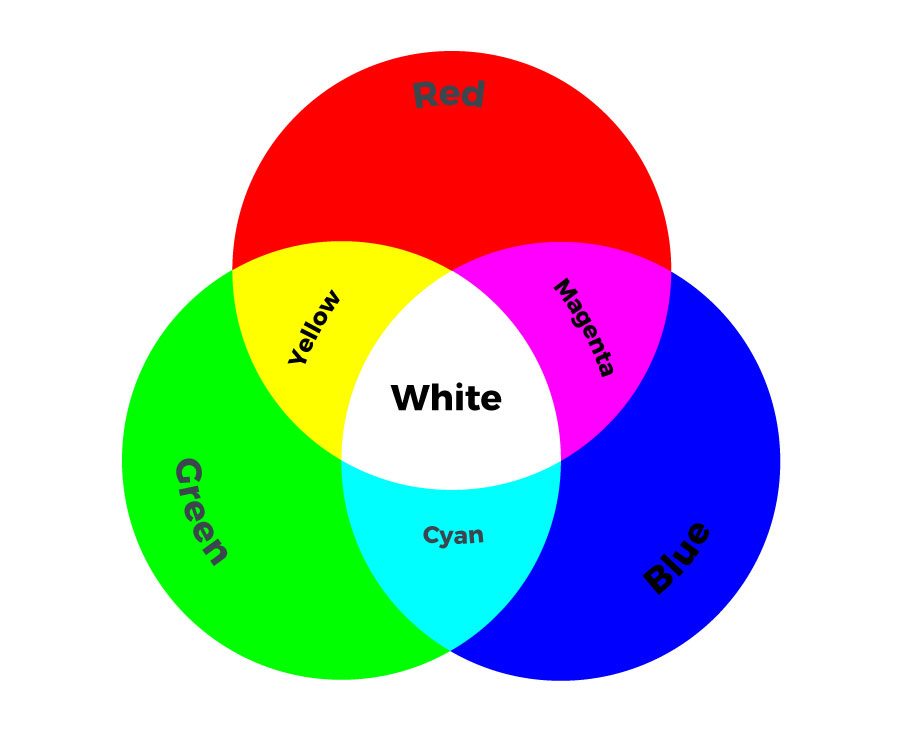
You probably noticed that your LilyMini has a built-in LED that it uses to tell you when it's turning on or off. This LED is special - it is actually 3 LEDs in one package - a red, a green, and a blue. This is why it's called a RGB (Red Green Blue) LED. The RGB LED can create many more colors than just red green and blue - When you turn on combinations of colors, they mix to create new colors!
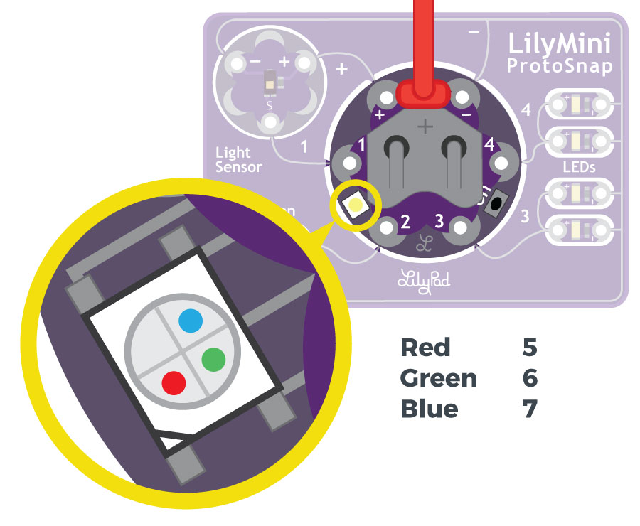
You can control this LED from your code like the white LED pairs you used in activities 1 and 2. Just like the sew tabs numbered 1 through 4 are able to be controlled by your program, the RGB LED is also attached to pins on the LilyMini: the red LED is pin 5, the green LED is pin 6, and the blue LED is pin 7.
Open the Color Mixing Example
Open the file named LilyMini_4_Color Mixing
Alternatively, you can copy and paste the following code into Arduino (be sure to erase everything already in the editing window first). Hit upload, and see what happens!
/*
LilyPad LilyMini ProtoSnap Activity 4: Color Mixing
SparkFun Electronics
https://www.sparkfun.com/products/14063
Make an RGB LED display a rainbow of colors!
An RGB LED is actually three LEDs (red, green, and blue) in
one package. When you run them at different brightnesses,
the red, green and blue mix to form new colors.
The LilyMini has a built-in RGB LED between sew tabs 1 and 2.
Red - pin 5
Green - pin 6
Blue - pin 7
This example is based on:
This example code is in the public domain
******************************************************************************/
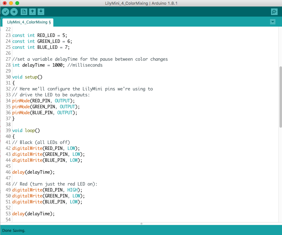
const int RED_LED = 5;
const int GREEN_LED = 6;
const int BLUE_LED = 7;
//set a variable delayTime for the pause between color changes
int delayTime = 1000; //milliseconds
// This variable controls how fast we loop through the colors.
// (Try changing this to make the fading faster or slower.)
void setup()
{
// Here we'll configure the LilyMini pins we're using to
// drive the LED to be outputs:
pinMode(RED_PIN, OUTPUT);
pinMode(GREEN_PIN, OUTPUT);
pinMode(BLUE_PIN, OUTPUT);
}
void loop()
{
// The first way is to turn the individual LEDs (red, blue,
// and green) on and off in various combinations. This gives you
// a total of eight colors (if you count "black" as a color).
// Black (all LEDs off)
digitalWrite(RED_PIN, LOW);
digitalWrite(GREEN_PIN, LOW);
digitalWrite(BLUE_PIN, LOW);
delay(delayTime);
// Red (turn just the red LED on):
digitalWrite(RED_PIN, HIGH);
digitalWrite(GREEN_PIN, LOW);
digitalWrite(BLUE_PIN, LOW);
delay(delayTime);
// Green (turn just the green LED on):
digitalWrite(RED_PIN, LOW);
digitalWrite(GREEN_PIN, HIGH);
digitalWrite(BLUE_PIN, LOW);
delay(delayTime);
// Blue (turn just the blue LED on):
digitalWrite(RED_PIN, LOW);
digitalWrite(GREEN_PIN, LOW);
digitalWrite(BLUE_PIN, HIGH);
delay(delayTime);
// Yellow (turn red and green on):
digitalWrite(RED_PIN, HIGH);
digitalWrite(GREEN_PIN, HIGH);
digitalWrite(BLUE_PIN, LOW);
delay(delayTime);
// Cyan (turn green and blue on):
digitalWrite(RED_PIN, LOW);
digitalWrite(GREEN_PIN, HIGH);
digitalWrite(BLUE_PIN, HIGH);
delay(delayTime);
// Purple (turn red and blue on):
digitalWrite(RED_PIN, HIGH);
digitalWrite(GREEN_PIN, LOW);
digitalWrite(BLUE_PIN, HIGH);
delay(delayTime);
// White (turn all the LEDs on):
digitalWrite(RED_PIN, HIGH);
digitalWrite(GREEN_PIN, HIGH);
digitalWrite(BLUE_PIN, HIGH);
delay(delayTime);
}
What You Should See
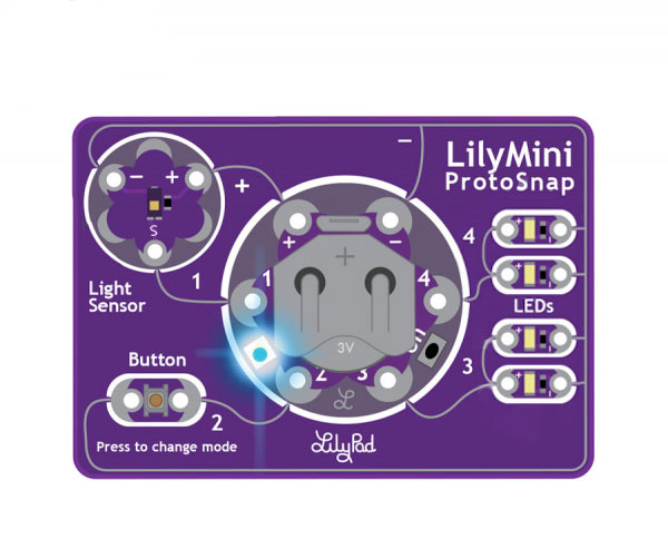
The RGB LED will cycle through the colors red, yellow, green, blue, cyan, purple, white, off. and repeat.
Understanding Your Program
int delayTime = 1000;
To slow things down a bit, there are delay() statements between every color change. These lets you get a good look at the color before it moves on to the next one. If we used actual numbers in all those delays, and you wanted to make everything faster or slower, you'd have to manually edit each one. But there's a handy shortcut you can use: create a variable called delayTime that is defined once, then used all the delay() statements. This way, you can change one number and every delay() will use it. Try changing the 1000 in the above statement to different numbers and uploading the new program!
digitalWrite(redPin, HIGH);
digitalWrite(greenPin, HIGH);
digitalWrite(bluePin, HIGH);
We've also created variables for redPin, greenPin, and bluePin so you don't have to remember that those LEDs are on pins 5, 6, and 7. Like the other LEDs, we use HIGH or LOW to turn the LEDs on or off.
Understanding Your Circuit
Inside the RGB LED are three smaller LEDs - red, green, and blue. If you look closely, you can see the tiny colored LEDs within the larger white LED. While these LEDs are not attached to sew tabs, they are connected back to the LilyMini's microcontroller chip in the same way. If you flip the LilyMini over, you'll see some white text reminding you which numbers connect to which LEDs. And if you look closely, you can follow the traces back to the chip (they sometimes hop from one side of the board to the other through tiny "tunnels" called vias).
Color Mixing
Turning on all three LEDs will create a white glow. This is called additive color because mixing light creates lighter colors, where mixing paint or pigments creates darker colors. Turning on different combinations of the red, green, and blue LEDs will create new (and sometimes unexpected) colors! If you are having trouble seeing the mixed color, try holding a piece of paper or translucent plastic over the LED to diffuse the light (white bottle caps or ping pong balls work well). If you want to diffuse it more permanently, put a dab of white or hot glue on top of the RGB LED.
Challenges and Going Further
- Can you change the speed of the rainbow using delayTime?
- Can you make a colored light pattern? (Police lights, Christmas colors, school colors, stop light, etc.)