DIY Heated Earmuffs
 Feldi
Feldi 
Understanding Your Circuit
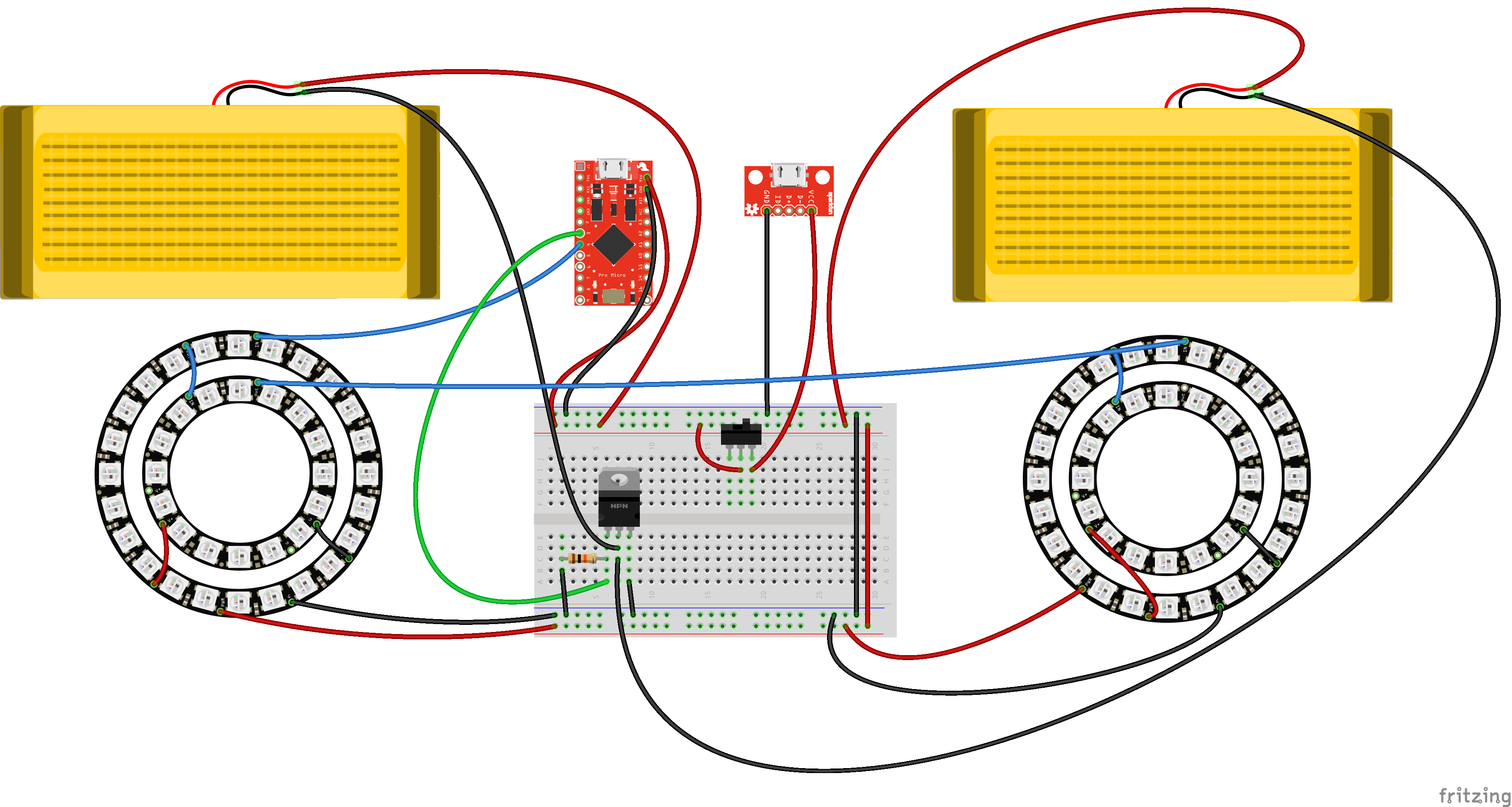
Inside the earmuffs are four NeoPixel Rings containing a total of 80 WS2812 addressable LEDs, two 5x10cm Heating Pads, a Pro Micro 5v/18MHz, a N-Channel MOSFET, one 10k resistor, two small pieces of Snappable Protoboard, and lots Hook Up Wire. The project is powered by our Lithium Ion Battery Pack via the SparkFun microB USB Breakout. A Mini Power Switch is connected to the power source for easy user control.
As expressed in the circuit diagram below, the Pro Micro 5v is the brains of this project. Pin 4 is connected to one of the 24x Neopixel Rings Din, with VCC connected to Raw on the Pro Micro, and GND to GND. Dout of that same Neopixel ring is connected to Din on of the 12x Neopixel Ring, VCC to VCC and GND to GND. Dout of the smaller Neopixel Ring is connected to Din on the second 24x Neopixel Ring, who's VCC and GND are connected to Raw and GND on the Microcontroller. Dout of this ring is connected to Din of the second 12x Neopixel ring, with VCC to VCC and GND to GND.
The heating pads require about ~750mA, which is more than the microcontroller I/O pin can handle. In order to accomplish that, we will be using a N-Channel Mosfet Transisitor. One lead of each of the heating pads should connect directly to RAW on the microcontroller. The second connects to the Drain (D) lead on the transistor, or the center lead. Pin 3 on the microcontroller connects to the Gain (G) lead, which is the left lead. There is also a 10k resistor pulling the G lead down to GND. Finally, the Source (S) lead connects directly to GND.
Two long flexible wires are included in the circuit. One connects to GND and one directly to Raw. The GND wire will connect to GND on the USB Breakout. The Raw wire will connect to the center lead of the switch. Finally VCC on the USB breakout will connect with a second lead on the switch.
The Heated Earmuffs pose a unique design challenge as a wearable circuit in that the components require a 5v power supply. That's not something you want to wear on your head. Because of this, the Heated Earmuffs have a similar physical design to headphones, with soft flexible wires connecting the circuit above with a control switch and power source in your pocket. Not only does this put the bulky power supply in a hidden location, but it also allows the user to conveniently and discretely switch the circuit on and off.