DIY Heated Earmuffs
 Feldi
Feldi 
Soldering It Together
Now that all of our parts are in place, let's begin to solder the circuit together.
STEP 23:
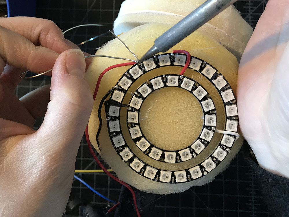
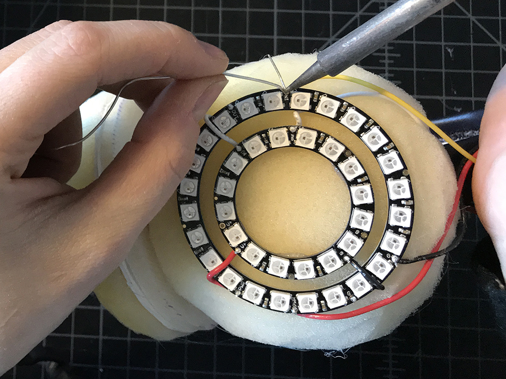
Take a long piece of hook up wire and solder one end to DOUT of one of your smaller NeoPixel Rings.
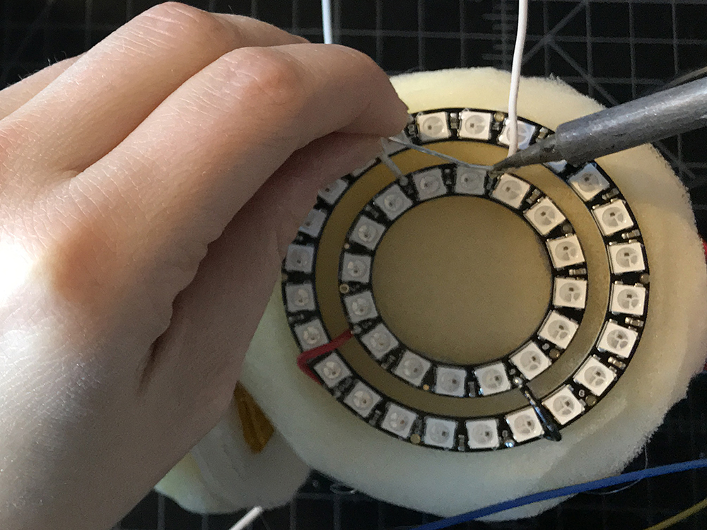
STEP 24:
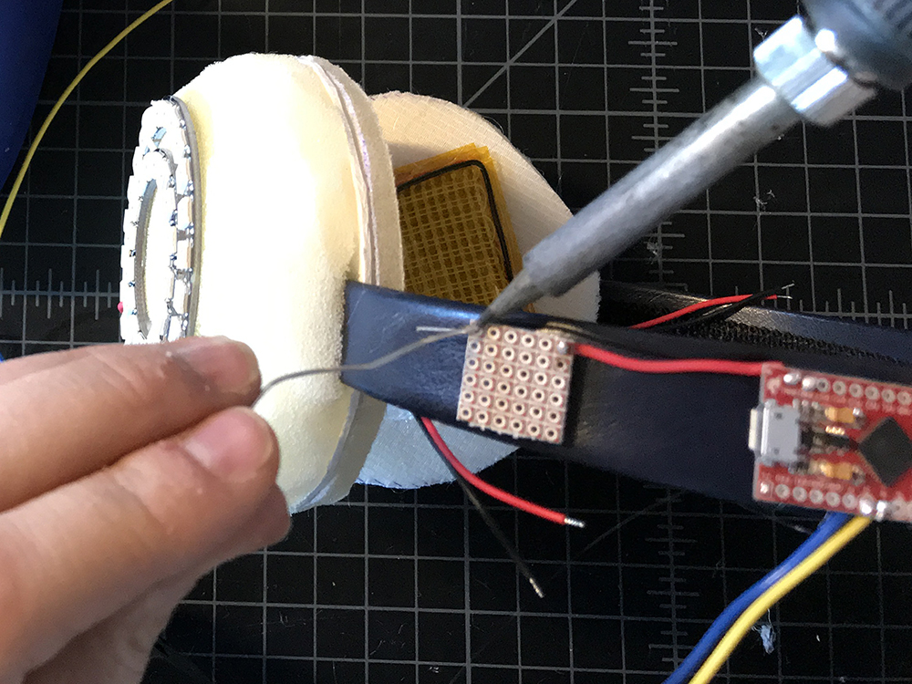
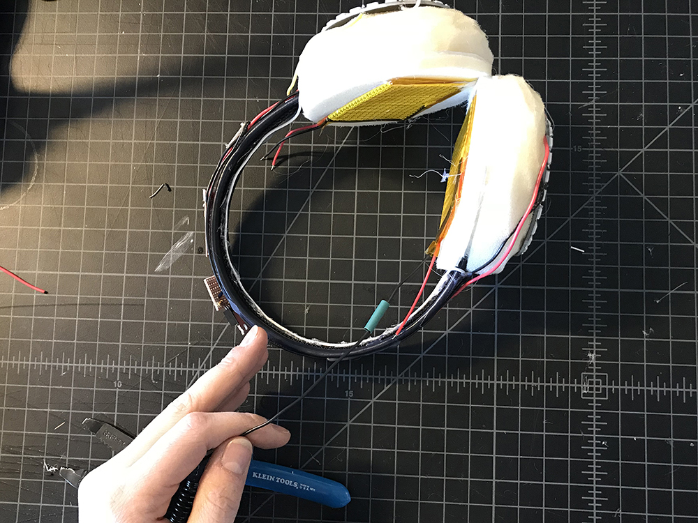
Lead it along the bottom edge of the headband, hot gluing it down along the way until you make it to the opposite side.
STEP 25:
Solder the other end to DIN of the larger ring on the opposite side. This in effect created one long LED strand of 80x WS2812 addressable LEDs.
STEP 26:
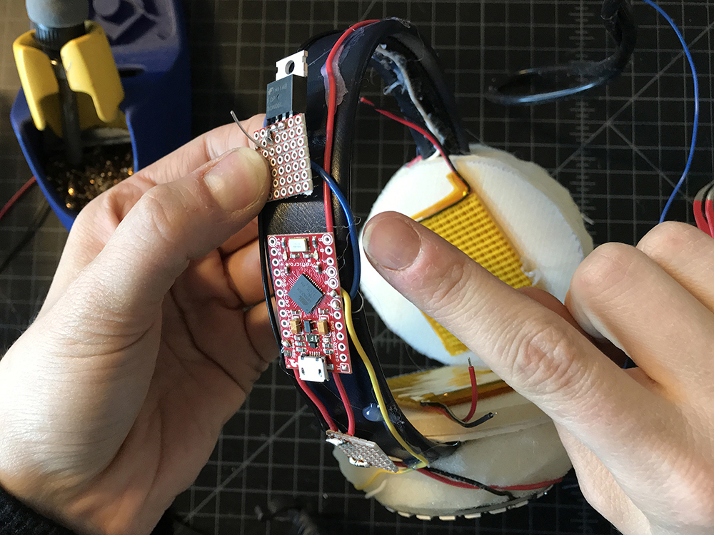
Cut the wire lead connected to Raw on the microcontroller down to about 1.5" - 2". Solder the free end to the corner of a piece of protoboard that is no wider than the headband. We will call this our Raw extension, and moving forward all connection to Raw will be made on this protoboard.
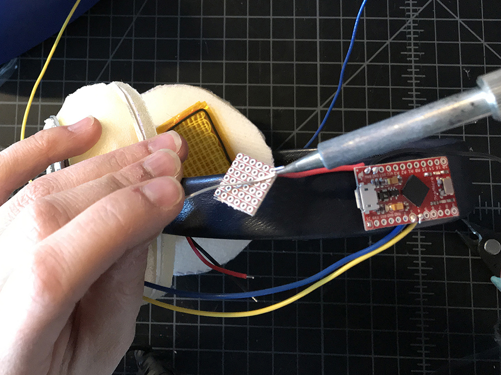
STEP 27:
Repeat step 26 for the GND wire lead. Make sure to solder it to the opposite end of the protoboard, leaving physical space between the two connections. We will call this our GND extension, and moving forward all connection to GND will be made on this protoboard.
STEP 28:
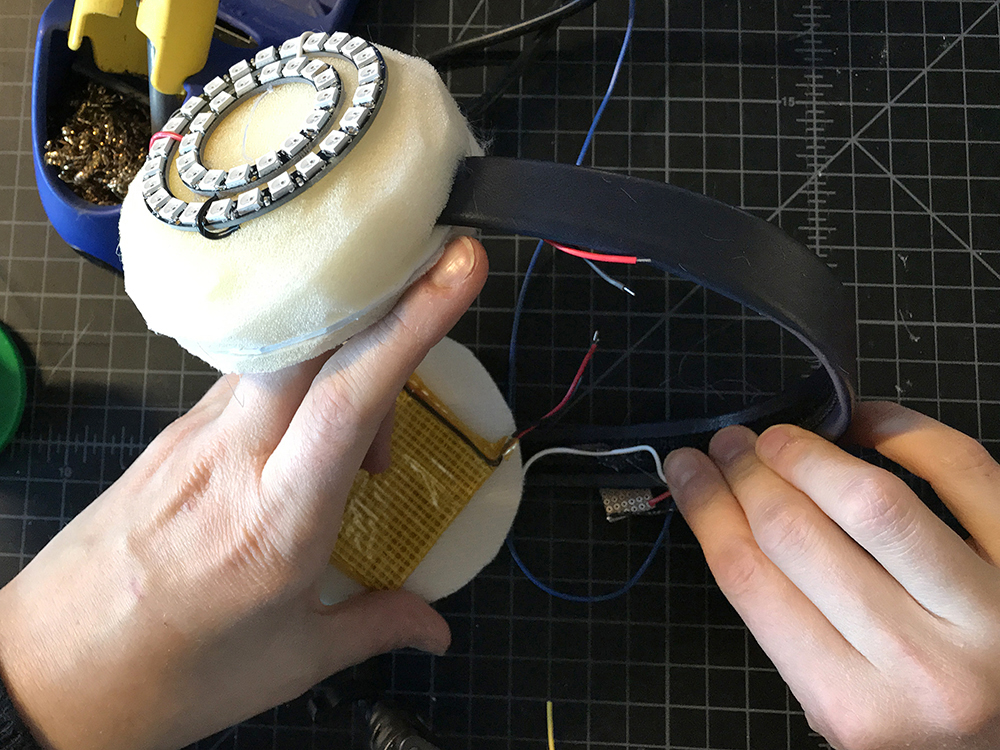
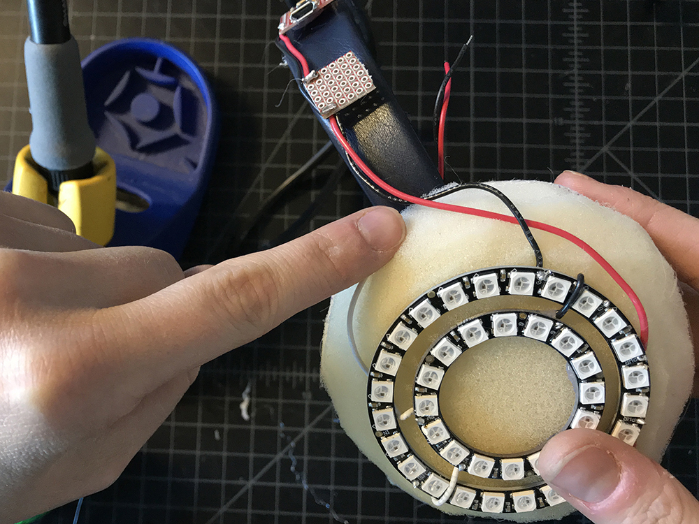
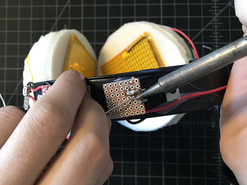
Solder a red wire lead to the Raw extension on the protoboard, and a black one to the GND extension. Take the red wire and solder it to VCC on one of the large Neopixel Rings. Take the black wire and solder it to GND on one of the large NeoPixel rings. Repeat for the second large ring on the opposite side.
While you are doing this, make sure to bend your wires to fit the form of the earmuffs.
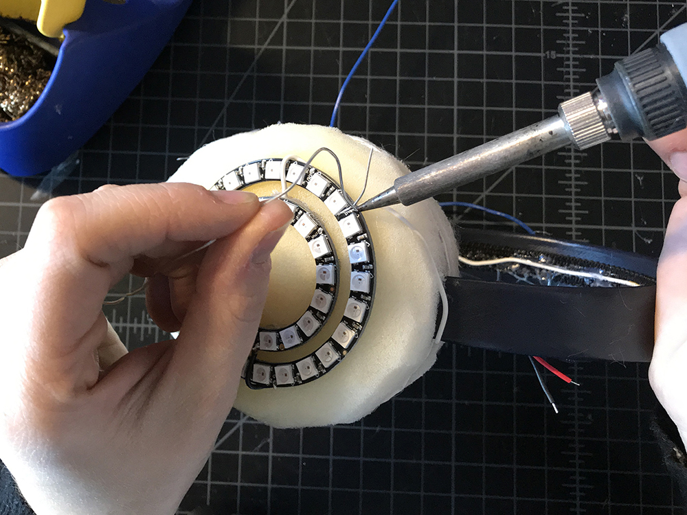
STEP 29:
Find the wire lead connected to pin 4.

Solder this wire to the remaining DIN on your NeoPixel Ring. As we have soldered the two sides together, there should only be on DIN left for you to use.
STEP 30:
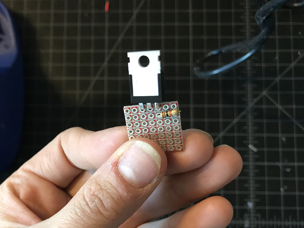
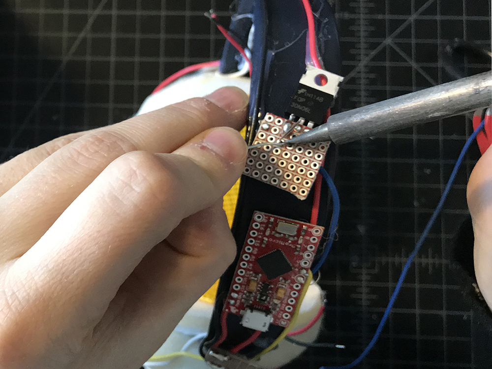
Cut a second small piece of protoboard, also no wider than the headband width, and solder the transistor along one edge.
STEP 31:
Trim the excess leads with a diagonal cutter and then fold the transistor back so that it lies flat in a plane with the protoboard.
STEP 32:
Solder a 10k resistor to the protoboard, connecting one end to the Gain (G) lead of the transistor and the other to a solder pad off to the side. Then use a jumper wire to solder the second side of the resistor to the GND extension.
STEP 33:
Holding the transistor protoboard to the headband with your thumb, solder the wire lead connected to pin 3 on the microcontroller to the same Gain (G) lead as the resistor on the transistor.
STEP 34:
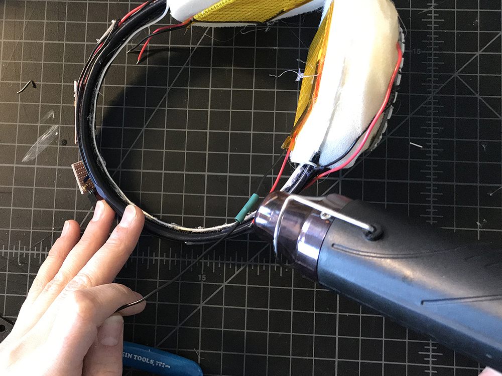
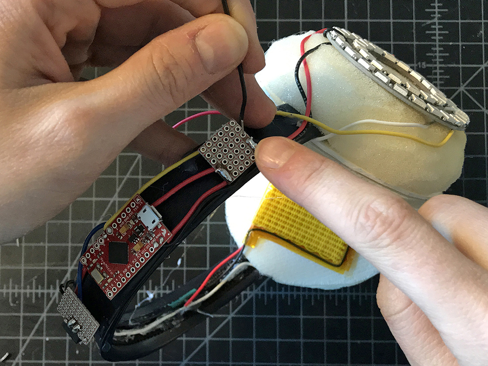
Take two medium pieces of red wire and two medium pieces of black wire. Solder each red wire to the red leads on the heating pads, and each black wire to the black leads on each heating pad, in essence fabricating longer leads for the heating pads.

STEP 35:
Place a small piece of heat shrink over each new connection and then use the heat gun to secure it around the soldered connections.
STEP 36:
Take both black leads from the heating pads and solder them to the middle lead on your transistor - also known as the Drain (D).
STEP 37:
Grab a medium black length wire and solder one end to the GND extension on the first protoboard.
STEP 38:
Solder the second end of that wire to the Source (S) or rightmost lead on the transistor.

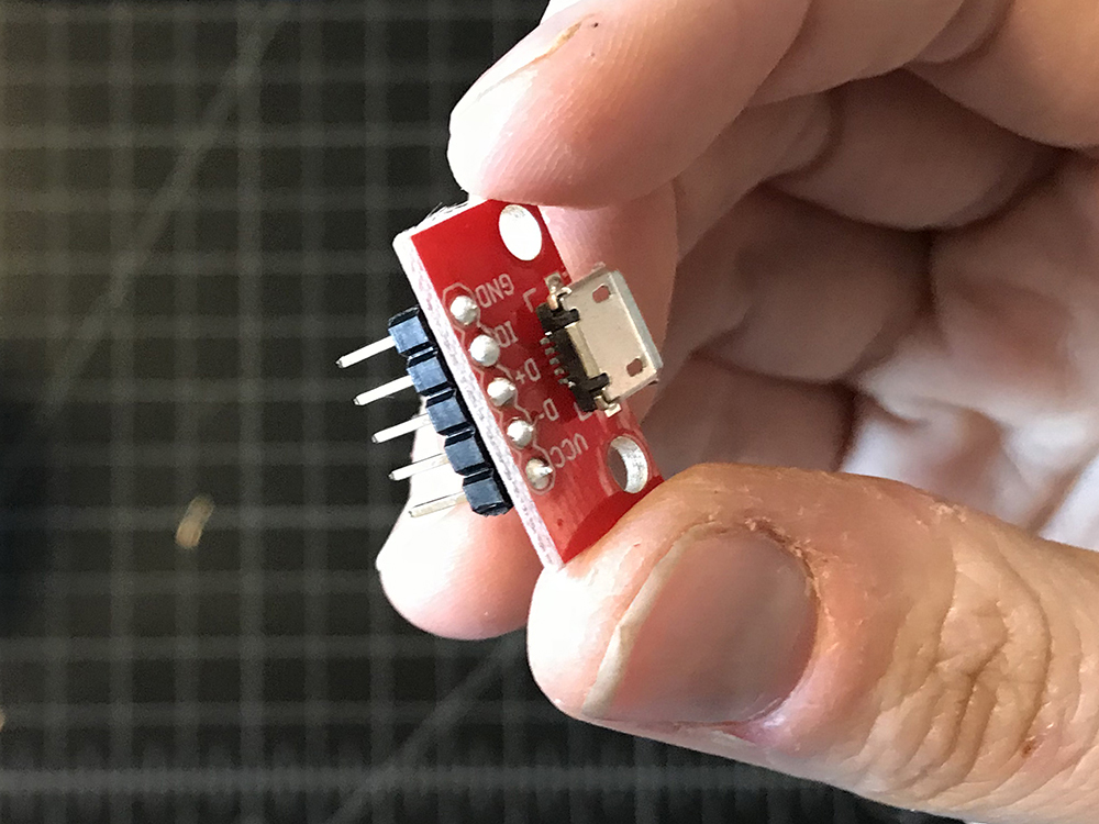
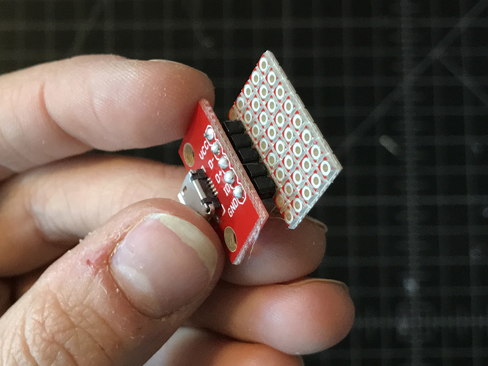
STEP 39:
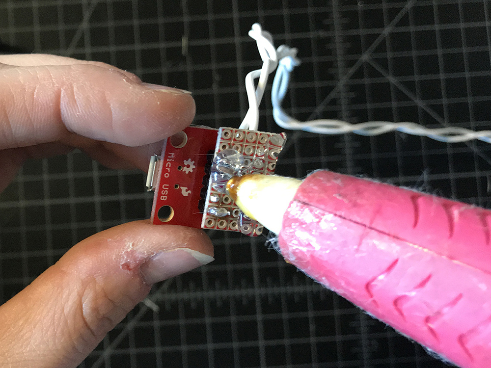
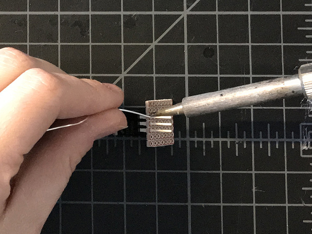
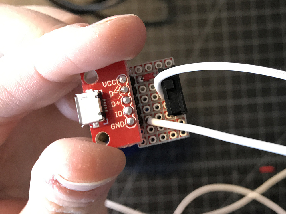
Solder header pins to your USB breakout.
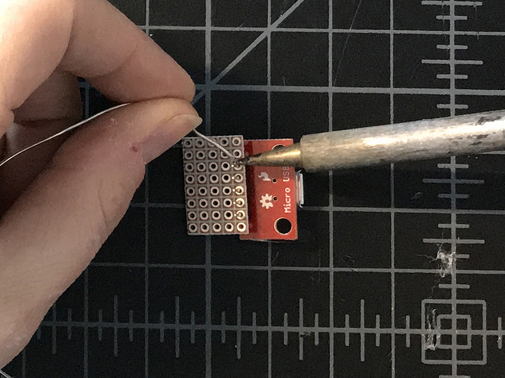
STEP 40:
Cut a third piece of protoboard slightly wider than your USB breakout, and solder the other end of the header pins to one edge.
STEP 41:
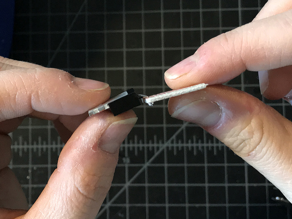
Solder the switch to the opposite edge of the protoboard.
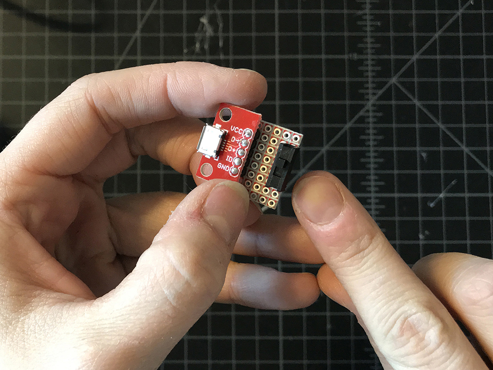
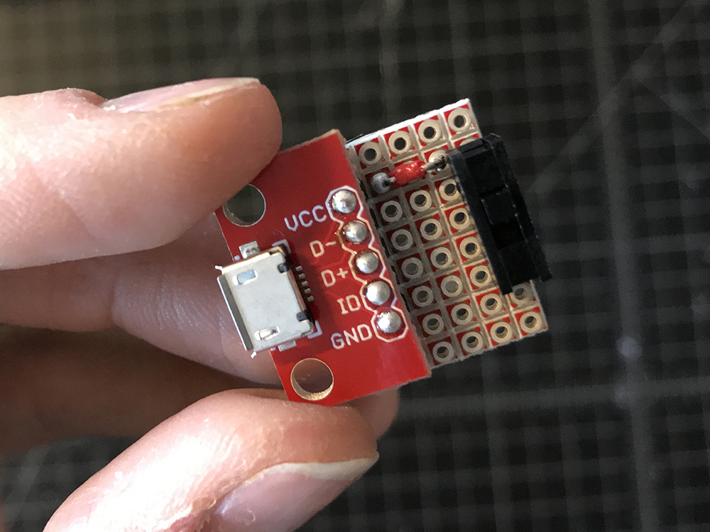
STEP 42:
Use a very small piece of wire to connect VCC on your breakout to either the leg on the rightmost or leftmost of the switch. It does not matter which.
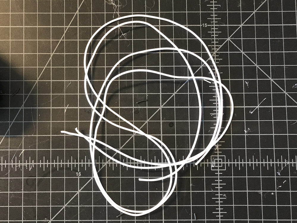
STEP 43:
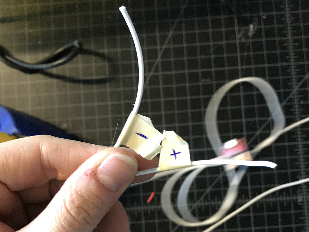
Cut two long pieces of silicone wire in white. These should be long enough to reach from the crown of your head to your pants pocket.
STEP 44:
Solder one wire to GND of the USB breakout, and the other to the middle lead of the switch. Label these right away with masking tape. The GND wire should be '-' and the Switch wire '+'.
STEP 45:
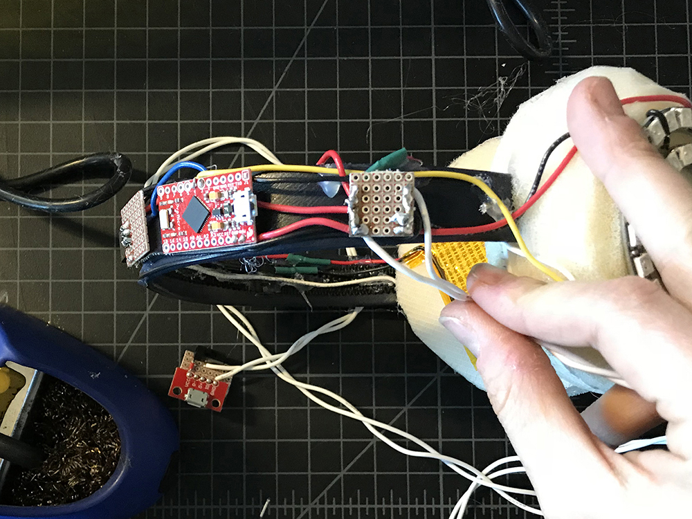
Twist the silicone wires lightly, the solder the '+' silicone lead to the Raw extension and the '-' silicone lead to the GND extension.
STEP 46:
Plug the battery pack into the USB port and switch your project on to test. This is to make sure that the solder joints are strong and that there are no shorts.
STEP 47:
Add hot glue to the bottom of the protoboard for insulation.