Digital Temperature Sensor Breakout - AS6212 (Qwiic) Hookup Guide
 QCPete,
  El Duderino
Hardware Overview
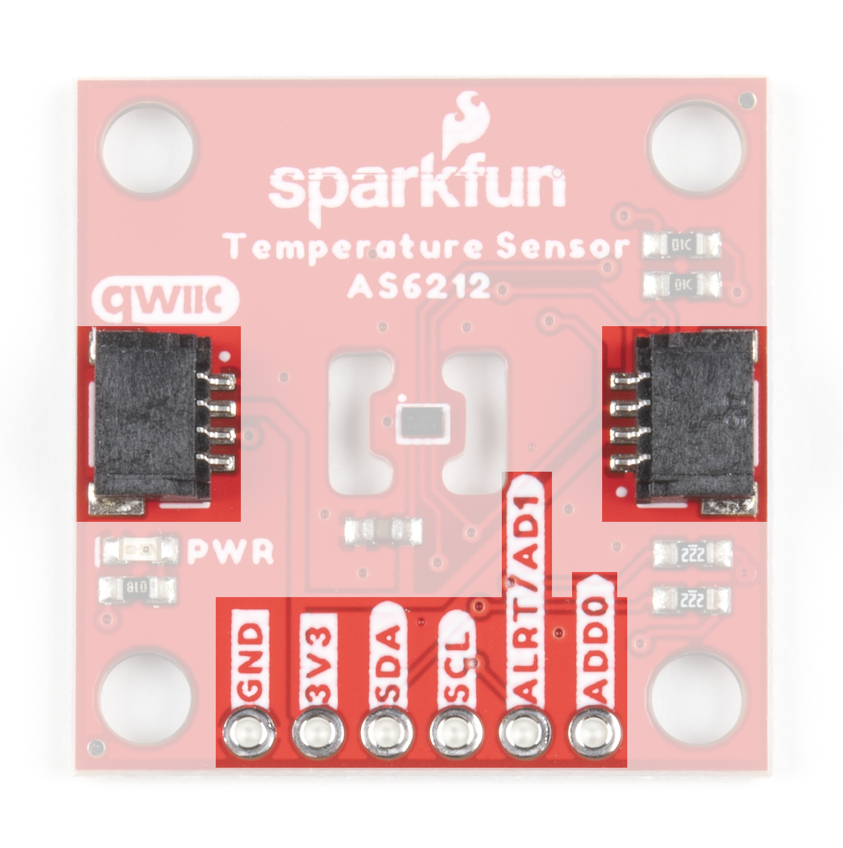
Let's take a closer look at the AS6212 temperature sensor and other hardware present on this Qwiic breakout.
AS6212 Digital Temperature Sensor
The AS6212 is a highly accurate and power efficient digital temperature sensor with a wide temperature sensing range (-40°C to 125°C) from ams AG. The AS6212 boasts a host of features including a configurable alert pin that can trigger when temperature data exceeds user-defined temperature thresholds. Read more on configuring the alert pin and temperature thresholds in the Arduino and Python sections of this guide as well as in the AS6212 Datasheet. The AS6212 also features a sleep/low power mode that works in tandem with a Single Shot measurement mode to wake the device, retrieve stored temperature data and return it to sleep mode.

The AS6212 accepts a supply voltage between 1.7V and 3.6 and typically consumes 6µA during normal temperature conversions and 0.1µA on standby. The AS6212 normally runs at 3.3V and receives power either through the Qwiic connectors or the dedicated 3.3V and GND PTH pins.
The breakout design isolates the AS6212 from the rest of the PCB as much as possible to minimize ambient heat from interfering with temperature data. The table below outlines the temperature data accuracy across the AS6212's temperature measurement range:
| Temperature Range | Temperature Accuracy |
|---|---|
| −10°C to 65°C | ±0.2°C |
| −40°C to −10°C and 65°C to 85°C | ±0.3°C |
| 85°C to 125°C | ±0.5°C |
I2C and Qwiic Interface
As the name of this breakout suggests, the board routes the AS6212's I2C pins to a pair of Qwiic connectors as well as a 0.1"-spaced PTH header for users who prefer a soldered connection. The AS6212 supports both fast (max 400kHz) and high-speed (max 3.4MHz) clock frequencies and has eight configurable I2C addresses (default is 0x48). Select the address by adjusting the labeled jumpers covered in the next section.
The Alert/AD1 and AD0 pins are also broken out to the same PTH header as the I2C pins to interact with. The Alert pin can be enabled to act as an external hardware interrupt for an attached microcontroller.
Solder Jumpers
The Digital Temperature Sensor Breakout - AS6212 (Qwiic) has four solder jumpers labeled LED, I2C, AD0 and AD1. The LED jumper connects the Power LED anode to 3.3V via a 1kΩ resistor. The jumper is CLOSED by default. Open the jumper to disable the Power LED and reduce the total current draw of the board. The I2C jumper ties the SDA and SCL lines to 3.3V via a pair of 2.2kΩ resistors and is CLOSED by default. Open the jumper to disable the pull-up resistors.
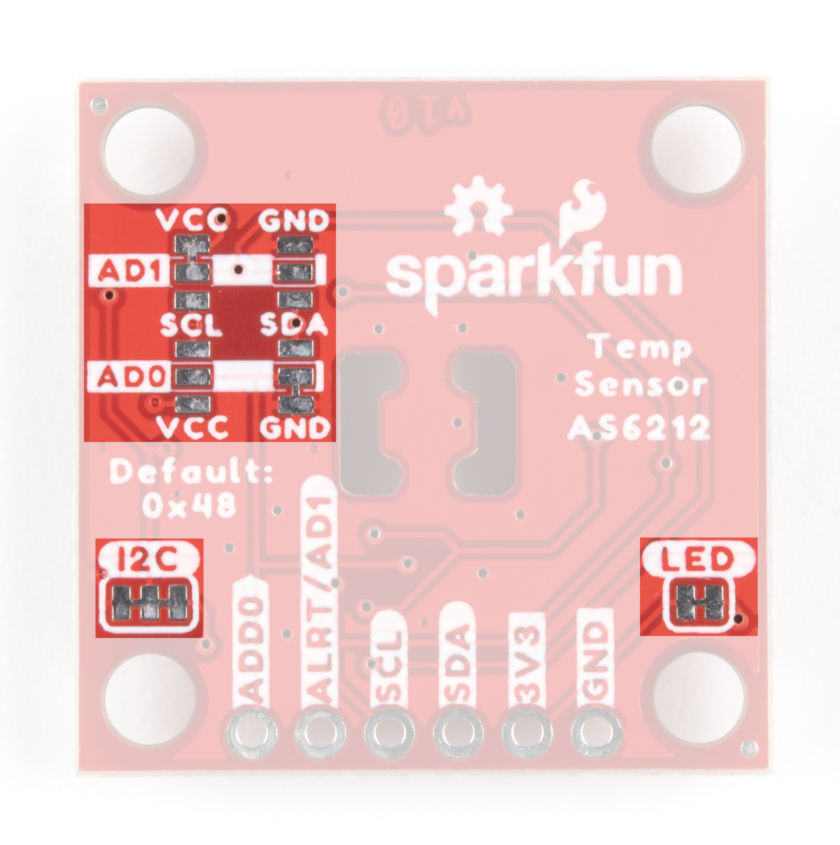
The AD0 and AD1 jumpers control the I2C address as well as enabling/disabling the Alert pin. By default, these two-way jumpers connect the AD0 pin to Ground and the Alert/AD1 pin to 3.3V to enable the Alert pin and set the I2C address to 0x48. Adjust these jumpers to change the address and/or disable the Alert pin. The table below outlines the various settings these jumpers can be set to:
| ALERT/AD1 Jumper Net | AD0 Jumper Net | Alert Pin Functionality | I2C Address |
|---|---|---|---|
| VCC (PU) | GND | Enabled | 0x48 (Default) |
| VCC (PU) | VCC | Enabled | 0x49 |
| VCC (PU) | SDA | Enabled | 0x4A |
| VCC (PU) | SCL | Enabled | 0x4B |
| SCL | GND | Disabled | 0x44 |
| SCL | VCC | Disabled | 0x45 |
| SCL | SDA | Disabled | 0x46 |
| SCL | SCL | Disabled | 0x47 |
| GND | GND | Disabled | 0x48 |
| GND | VCC | Disabled | 0x49 |
| GND | SDA | Disabled | 0x4A |
| GND | SCL | Disabled | 0x4B |
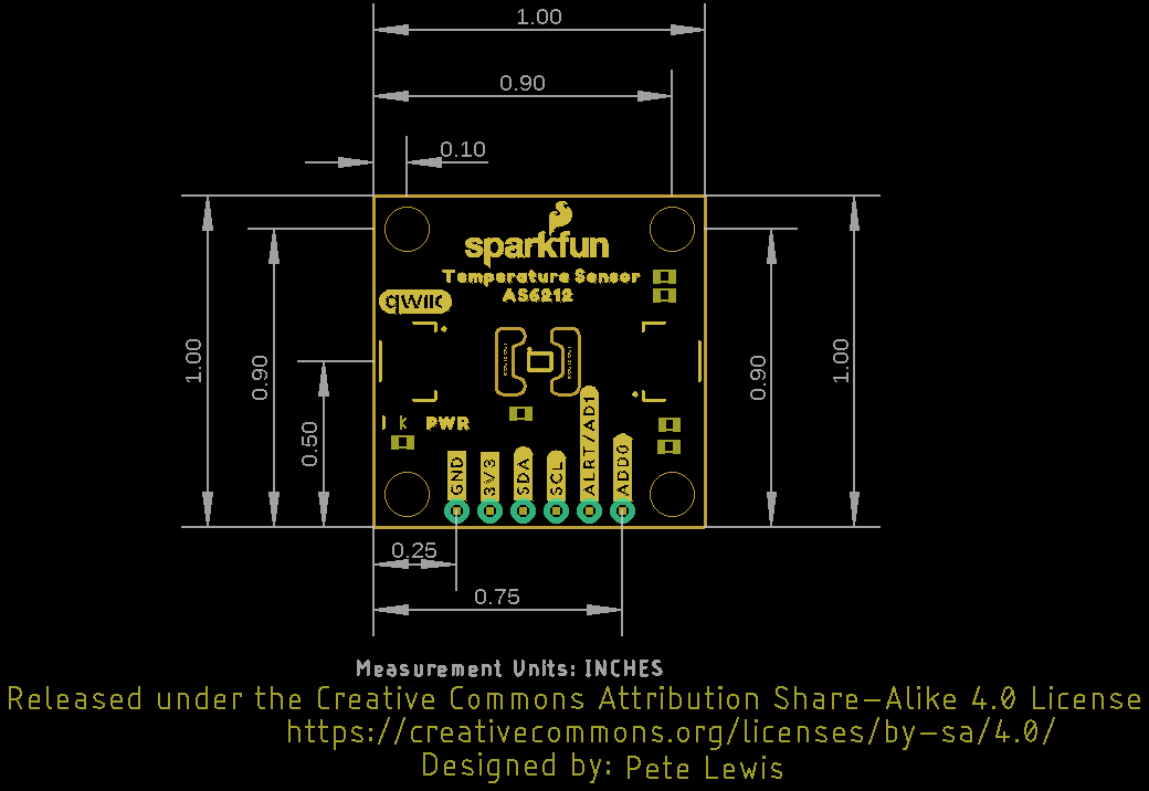
Board Dimensions
The Digital Temperature Sensor Breakout - AS6212 (Qwiic) matches the 1" x 1" (25.4mm x 25.4mm) standard form-factor for most of SparkFun's Qwiic breakouts and has four mounting holes that fit 4-40 screws.