Digital Temperature Sensor Breakout - AS6212 (Qwiic) Hookup Guide
 QCPete,
  El Duderino
 Introduction
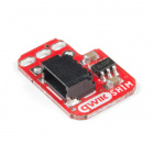
The SparkFun Digital Temperature Sensor Breakout - AS6212 (Qwiic) provides a combination of high temperature accuracy with excellent low power consumption using the AS6212 digital temperature sensor from ams AG. The AS6212 measures temperature with ±0.2°C accuracy between -10°C to 65°C (full measurement range is -40°C to 125°C), consumes an average of 6µA (0.1µA in standby) and communicates over I2C so naturally we put it on a Qwiic breakout to add to our ever expanding Qwiic system. All of this in a tiny IC package measuring 1.5mm x 1mm.
Required Materials
In order to follow along with this tutorial you'll need a few items along with the AS6212 breakout.
First off, the Digital Temperature Sensor Breakout - AS6212 (Qwiic) needs a controller like an Arduino development board or single-board computer (SBC) like a Raspberry Pi to communicate with the board. Click the button below to toggle to recommended Raspberry Pi and Qwiic Pi products.
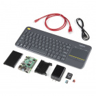
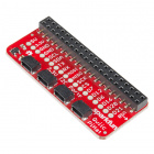
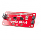
Raspberry Pi Materials (Toggle)


Along with a development board or SBC, you'll need at least one Qwiic cable. SparkFun carries a variety of lengths and types of Qwiic cables as seen here:

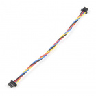

Qwiic Cable - 100mm
PRT-14427
Qwiic Cable - 200mm
PRT-14428Recommended Reading
In case you are not familiar with the Qwiic System, we recommend reading here for an overview:
We also recommend taking a look at the following tutorials if you aren't familiar with the concepts covered in them:
Logic Levels
I2C
Serial Terminal Basics
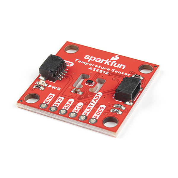
Hardware Overview
Let's take a closer look at the AS6212 temperature sensor and other hardware present on this Qwiic breakout.
AS6212 Digital Temperature Sensor
The AS6212 is a highly accurate and power efficient digital temperature sensor with a wide temperature sensing range (-40°C to 125°C) from ams AG. The AS6212 boasts a host of features including a configurable alert pin that can trigger when temperature data exceeds user-defined temperature thresholds. Read more on configuring the alert pin and temperature thresholds in the Arduino and Python sections of this guide as well as in the AS6212 Datasheet. The AS6212 also features a sleep/low power mode that works in tandem with a Single Shot measurement mode to wake the device, retrieve stored temperature data and return it to sleep mode.

The AS6212 accepts a supply voltage between 1.7V and 3.6 and typically consumes 6µA during normal temperature conversions and 0.1µA on standby. The AS6212 normally runs at 3.3V and receives power either through the Qwiic connectors or the dedicated 3.3V and GND PTH pins.
The breakout design isolates the AS6212 from the rest of the PCB as much as possible to minimize ambient heat from interfering with temperature data. The table below outlines the temperature data accuracy across the AS6212's temperature measurement range:
| Temperature Range | Temperature Accuracy |
|---|---|
| −10°C to 65°C | ±0.2°C |
| −40°C to −10°C and 65°C to 85°C | ±0.3°C |
| 85°C to 125°C | ±0.5°C |
I2C and Qwiic Interface
As the name of this breakout suggests, the board routes the AS6212's I2C pins to a pair of Qwiic connectors as well as a 0.1"-spaced PTH header for users who prefer a soldered connection. The AS6212 supports both fast (max 400kHz) and high-speed (max 3.4MHz) clock frequencies and has eight configurable I2C addresses (default is 0x48). Select the address by adjusting the labeled jumpers covered in the next section.
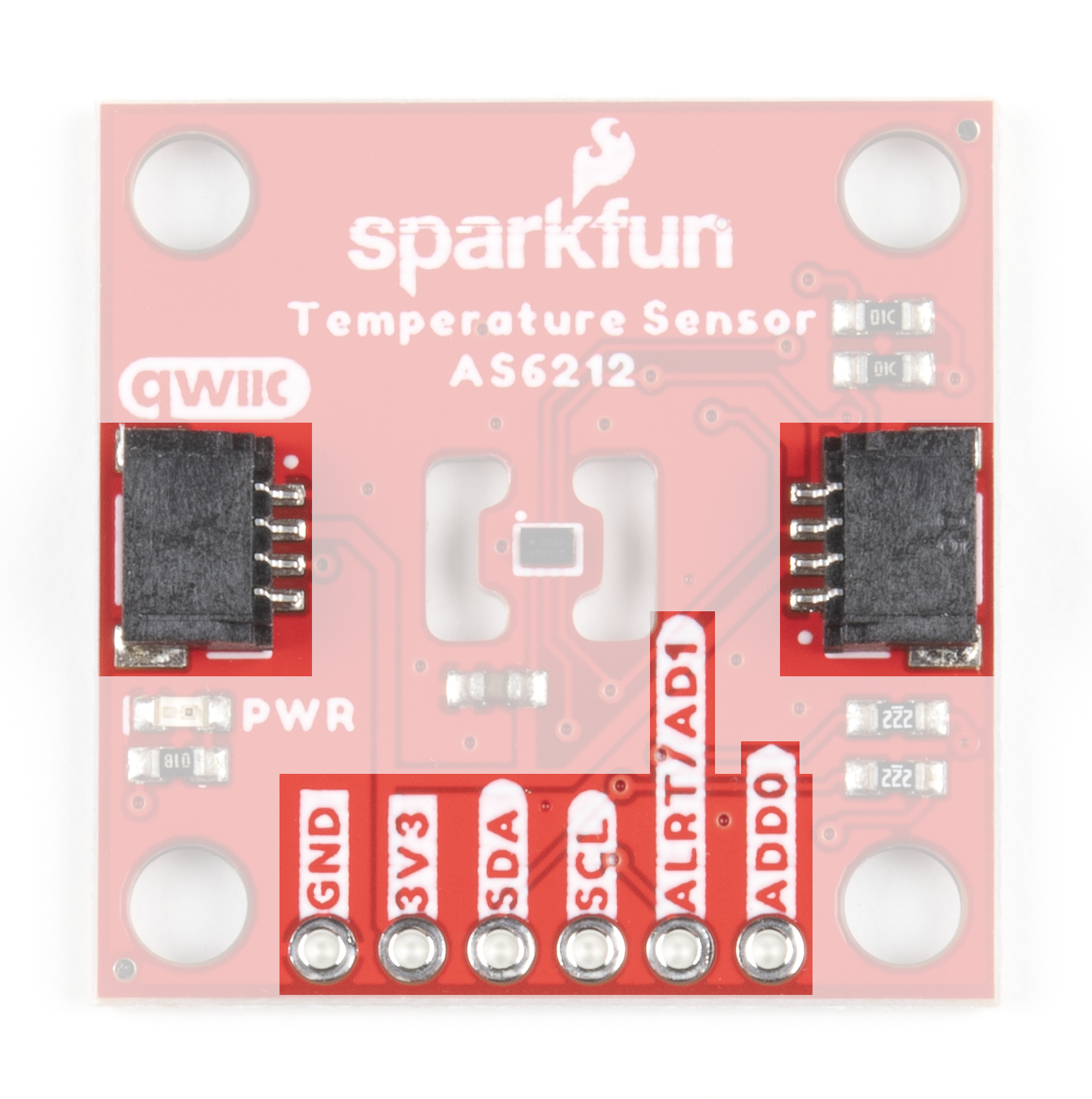
The Alert/AD1 and AD0 pins are also broken out to the same PTH header as the I2C pins to interact with. The Alert pin can be enabled to act as an external hardware interrupt for an attached microcontroller.
Solder Jumpers
The Digital Temperature Sensor Breakout - AS6212 (Qwiic) has four solder jumpers labeled LED, I2C, AD0 and AD1. The LED jumper connects the Power LED anode to 3.3V via a 1kΩ resistor. The jumper is CLOSED by default. Open the jumper to disable the Power LED and reduce the total current draw of the board. The I2C jumper ties the SDA and SCL lines to 3.3V via a pair of 2.2kΩ resistors and is CLOSED by default. Open the jumper to disable the pull-up resistors.
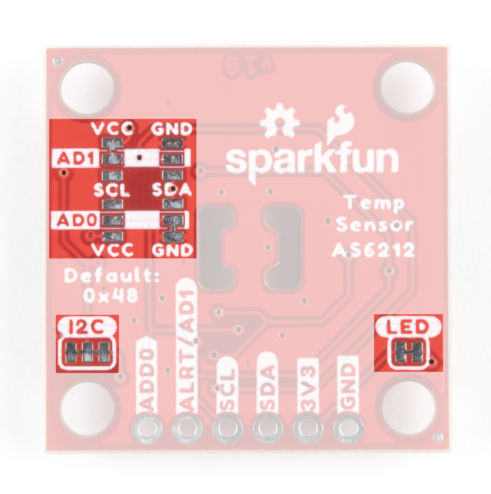
The AD0 and AD1 jumpers control the I2C address as well as enabling/disabling the Alert pin. By default, these two-way jumpers connect the AD0 pin to Ground and the Alert/AD1 pin to 3.3V to enable the Alert pin and set the I2C address to 0x48. Adjust these jumpers to change the address and/or disable the Alert pin. The table below outlines the various settings these jumpers can be set to:
| ALERT/AD1 Jumper Net | AD0 Jumper Net | Alert Pin Functionality | I2C Address |
|---|---|---|---|
| VCC (PU) | GND | Enabled | 0x48 (Default) |
| VCC (PU) | VCC | Enabled | 0x49 |
| VCC (PU) | SDA | Enabled | 0x4A |
| VCC (PU) | SCL | Enabled | 0x4B |
| SCL | GND | Disabled | 0x44 |
| SCL | VCC | Disabled | 0x45 |
| SCL | SDA | Disabled | 0x46 |
| SCL | SCL | Disabled | 0x47 |
| GND | GND | Disabled | 0x48 |
| GND | VCC | Disabled | 0x49 |
| GND | SDA | Disabled | 0x4A |
| GND | SCL | Disabled | 0x4B |
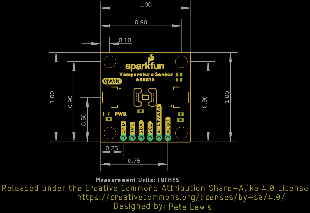
Board Dimensions
The Digital Temperature Sensor Breakout - AS6212 (Qwiic) matches the 1" x 1" (25.4mm x 25.4mm) standard form-factor for most of SparkFun's Qwiic breakouts and has four mounting holes that fit 4-40 screws.
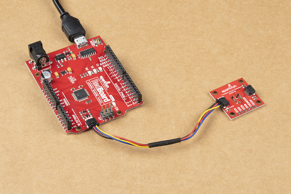
Hardware Assembly
Assembling your temperature sensing circuit with the Qwiic system is simple. Just connect your SparkFun Digital Temperature Sensor Breakout - AS6212 (Qwiic) to your chosen development board or single-board computer with a Qwiic cable or adapter cable.
Users who prefer a traditional through-hole connection can solder the PTH pins broken out on the board. Reminder, the Alert/AD1 Pin is not connected to the Qwiic connector so it requires a separate connection to the Alert PTH pin for use. Alternatively, if you want a temporary connection for prototyping, these IC Hooks are a great option to make that connection. If you are not familiar with through-hole soldering take a look at this tutorial:
How to Solder: Through-Hole Soldering
With the AS6212 connected to your microcontroller it's time to get some code uploaded and start taking temperature measurements!
Qwiic AS6212 Arduino Library
The SparkFun AS6212 Arduino Library helps users configure and pull temperature data from the AS6212. Install the library through the Arduino Library Installer by searching for "SparkFun AS6212". Users who prefer to manually install the library can find it on the GitHub Repository or can download a .ZIP of the repo by clicking the button below:
Library Functions
The list below outlines the functions included in the AS6212 Arduino Library along with short descriptions of what they do.
Class
Construct the AS6212 object in the global class. The examples use sensor as the AS6212 breakout object.
AS6212 sensor;
Device Setup and Settings
bool begin(uint8_t sensorAddress, TwoWire &wirePort);- Initialize the AS6212 Qwiic breakout at a specified address on a selected port. If left empty, default values are used for the address (0x48) and Wire port.bool setDefaultSettings();- Set the AS6212 CONFIG register to default/factory settings. This helps quickly return the sensor to default settings if anything in the CONFIG register has been changed as adjustments to the CONFIG register remain through power cycles.uint8_t getAddress();- Returns the device's I2C address.bool getAlertStatus();- Returns the status of the Alert bit.void setConsecutiveFaults(int faults);- Sets the number of consecutive faults (temperature aboveTHigh) to occur before the Alert pin state adjusts. Acceptable values are 1,2,3 and 4.uint8_t getConsecutiveFaults();- Returns the value set forsetConsecutiveFaults();.void setInterruptMode(bool mode);- Set the AS6212 Alert pin to operate in Interrupt mode.bool getInterruptMode();- Read whether the Alert pin is set to operate in Interrupt mode.void setConversionCycleTime(uint8_t cycleTime = AS6212_CONVERSION_CYCLE_TIME_250MS);- Sets the time between temperature conversions in milliseconds. Acceptable entries are: 125MS, 250MS, 1000MS or 4000MS.uint16_t getConversionCycleTime();- Returns the value set for Conversion Cycle Time in milliseconds.void setAlertPolarity(bool polarity);- Set the polarity of the Alert pin output to go eitherHIGHorLOWwhen triggered. Default isLOW/0.bool getAlertPolarity();- Returns the value set for the Alert polarity bit.0for active LOW or1for active HIGH.void sleepModeOn();- Put the AS6212 into Sleep Mode. The device must be in Sleep Mode for Single Shot measurements to be made.void sleepModeOff();- Clears the Sleep Mode bit in the config register and after reseting the SM bit to0the device returns to continuous conversion mode.bool getSleepMode();- Returns the Sleep Mode bit status as a boolean.void triggerSingleShotConversion();- Tell the AS6212 to perform a Single Shot temperature conversion.bool getSingleShotStatus();- Returns the Single Shot mode bit status as a boolean.0for no conversion ongoing/conversion finished.1for start Single Shot conversion/conversion ongoing.void setConfig(uint16_t targetState);- Legacy function for users who wish to interact directly with the CONFIG register. Refer to section 6.2 in the AS6212 Datasheet for a detailed description of this regsiter and the adjustable bits in it.uint16_t readConfig();- Returns the settings in the CONFIG register as an unsigned integer.
Temperature Data
float readTempC();- Returns the recorded temperature in degrees Celsius.float getTLowC();- Returns the temperature value set forsetTLowC.bool setTLowC(int16_t lowLimit);- Sets the temperature in °C for low temperature threshold. Used for the alert pin temperature limits.float getTHighC();- Returns the temperature value set forsetTHighC.bool setTHighC(int16_t highLimit);- Sets the temperature in °C for the high temperature threshold. Used for the alert pin temperature limits.float readTempF();- Returns the recorded temperature in degrees Fahrenheit.float getTLowF();- Returns the temperature value set forsetTLowF.bool setTLowF(int16_t lowLimit);- Sets the temperature in °F for low temperature threshold. Used for the alert pin temperature limits.float getTHighF();- Returns the temperature value set forsetTHighF.bool setTHighF(int16_t highLimit);- ets the temperature in °F for high temperature threshold. Used for the alert pin temperature limits.
Arduino Examples
The SparkFun AS6212 Arduino Library includes ten examples to showcase the various capabilities and settings of the AS6212. In this section we'll take an in-depth look at most of those examples and highlight pertinent bits of code where necessary. The examples build on each other so it may help to go through them in sequential order.
Prior to uploading the examples, let's take a quick look at the setup function used in all examples:
language:c
if (sensor.begin() == false)
{
    Serial.println("AS6212 Qwiic failed to respond. Please check wiring and possibly the I2C address. Freezing...");
    while (1);
};
After uploading any of the examples, open the Arduino serial monitor with the baud set to 115200. If the AS6212 fails to initialize on the bus, the code freezes and prints out "AS6212 Qwiic failed to respond. Please check wiring and possibly the I2C address. Freezing...".
If you see this message, check the connection between the breakout and controller and make sure the AS6212 is either set to the default address or the sensor.begin(); function is adjusted to the correct address. Refer to Example 2 - Different I2C Address for a quick demonstration of initializing the AS6212 on an alternate address.
Each example also includes a quick call of the setDefaultSettings(); function to return the AS6212 to default settings as adjustments to the CONFIG register (e.g. conversion cycle time, interrupt mode, alert pin polarity) remain through power cycles.
Example 1 - Basic Readings
The first example in the library demonstrates how to initialize the AS6212 on the I2C bus and retrieve temperature data from the sensor in both °C and °F. Open the example by navigating to File > Examples > SparkFun AS6212 Arduino Library > Example_01_BasicReadings. Select the appropriate Board and Port and click upload. Assuming the upload was successful, open the serial monitor with the baud set to 115200.
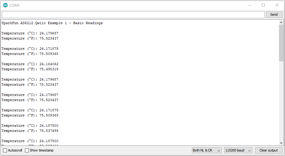
After initializing, the code prints out temperature data recorded by the AS6212 in both °C and °F every second. Try breathing on the sensor or gently press your finger to it and watch the temperature data change.
Example 3 - Sleep
Example 3 demonstrates how to put the AS6212 in and out of Sleep Mode with default settings. Note, this example keeps the default settings so the AS6212 measures in continuous mode when awake. Take a look at the next example for use of the Single Shot readings for maximum power efficiency.
The main loop creates a wake/sleep loop with a 150ms delay after waking to ensure temperature current and accurate temperature data. Without this delay the first values read will be from the last time the AS6212 was awake. Once woken up, the code returns temperature data for both Celsius and Fahrenheit and then puts the AS6212 back into Sleep Mode for five seconds.
Example 4 - Single Shot Readings
Example 4 builds on the previous example to combine Sleep Mode with Single Shot readings to maximize power efficiency. The example starts similarly to Example 3 but includes an extra two lines in the setup to start with the AS6212 in Sleep Mode to enable Single Shot readings.
language:c
sensor.sleepModeOn();
delay(150);
With the sensor in Sleep Mode, the code triggers a Single Shot reading. Note, this automatically returns the AS6212 to sleep mode once complete.:
language:c
sensor.triggerSingleShotConversion();
The code also includes a serial print to let the user know when a Single Shot conversion is ongoing and prints out the temperature data in both Celsius and Fahrenheit for each reading.
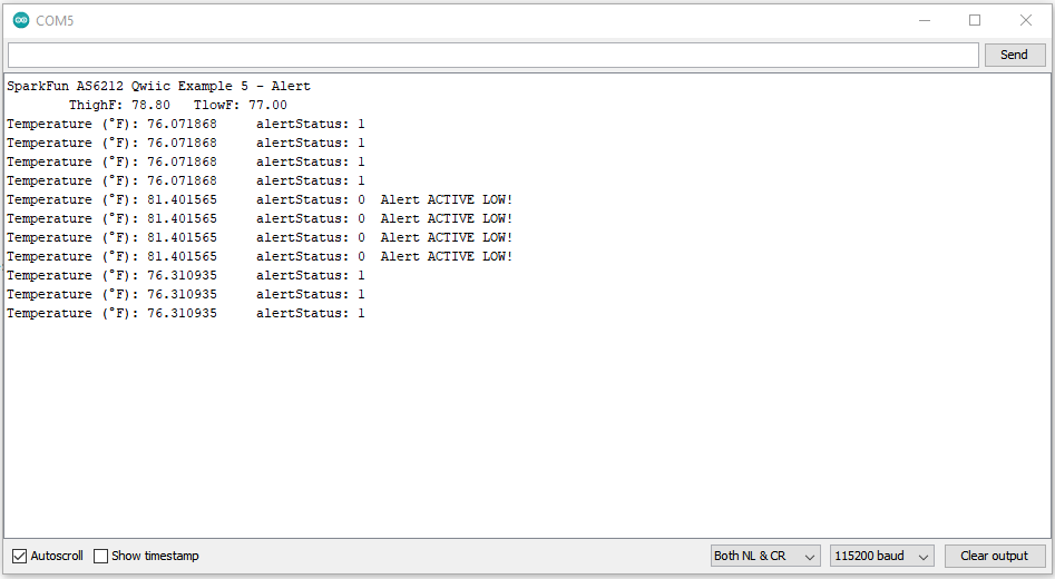
Example 5 - Alert
Example 5 shows how to set upper and lower temperature thresholds and how to enable/disable the Alert pin when the recorded temperature crosses those values. The code starts by checking to make sure the AS6212 is awake in case it was left in Sleep Mode from a previous example in this library. After checking that (and waking the sensor up if it was asleep), the code sets values for THighF(); and TLowF(); to 80°F and 77°F, respectively.
language:c
if (sensor.getSleepMode() == true)
{
    Serial.println("Sensor was asleep, waking up now");
    sensor.sleepModeOff();
    delay(150);
}

sensor.setTHighF(80);
sensor.setTLowF(77);
THigh and TLow thresholds have a specific resolution so you may notice that the code prints out a value slightly off of what was set for the threshold. Refer to section 6.2.9 in the AS6212 Datasheet for more specific information on the High and Low Limit Registers.
The code sets these values close together specifically to easily test the threshold settings by breathing on the sensor lightly to raise the temperature above the threshold. The main loop prints the temperature data and watches the alert status. When the temperature crosses the THigh threshold, the Alert pin goes LOW and remains LOW until the temperature drops below the TLow threshold. The code also prints out the status of the Alert pin.
language:c
void loop() {
    tempF = sensor.readTempF();
    Serial.print("Temperature (°F): ");
    Serial.print(tempF, 6);              //Reads out 6 characters of the temperature float

    alertStatus = sensor.getAlertStatus();

    Serial.print("\talertStatus: ");
    Serial.print(alertStatus);

    if (alertStatus == false) // be default alertStatus is active low
    {
        Serial.print("\tAlert ACTIVE LOW!");
    }

    Serial.println();
    delay(1000);
}
Example 6 - Conversion Cycle Time
Now that we've used the high and low temperature thresholds to toggle the Alert pin, Example 6 shows how to adjust the conversion cycle time for Single Shot measurements to alter how long the temperature must stay above/below the set temperature thresholds to trigger the Alert pin. The example sets the conversion cycle time to once every four seconds while reading the alert status every second. With this setting, the temperature data must cross the threshold and stay there through the conversion before the Alert pin will fire.
language:c
sensor.setConversionCycleTime(AS6212_CONVERSION_CYCLE_TIME_4000MS);
Other options for this setting are 125MS (8 times/sec), 250MS (4 times/sec) and 1000MS (1 time/sec). The main loop performs the same alertStatus check as the previous example and if the temperature crosses the THigh threshold and stays there during the conversion cycle time, the alert pin will go LOW until the temperature drops below the TLow threshold and stays there through a conversion cycle.
Example 7 - Consecutive Faults
Further building on the alert examples, Example 7 demonstrates how to integrate the setConsecutiveFaults function into monitoring temperature data to trigger the Alert pin. Adding a consecutive fault check on top of the conversion cycle time setting allows you to really configure how long temperature must remain above/below the THigh and TLow thresholds to trigger the Alert pin. This example sets both the setConsecutiveFaults and setConversionCycleTime to their max values so the temperature must remain above the THigh threshold for 16 seconds for the Alert pin to go LOW. Note, this also means the Alert pin will remain LOW until the temperature data is below the TLow threshold for 16 seconds as well.
language:c
sensor.setConsecutiveFaults(4);
Allowable values for the setConsecutiveFaults function are 1,2,3 or 4. The main loop is the same as the previous two examples; temperature data prints and alertStatus is checked every second. If the temperature crosses the THigh threshold and stays there for four conversion cycles (16 seconds), the code prints "Alert ACTIVE LOW!" until the temperature drops below the TLow threshold for the same duration.
Example 8 - Interrupt Mode
Example 8 shows how to use the setInterruptMode function to switch between Comparator and Interrupt. The previous examples all use the default mode, Comparator, where the Alert pin changes state when temperature data crosses the THigh threshold and stays in the new state until the temperature drops below the TLow threshold. This example sets the Alert pin to operate in Interrupt mode:
language:c
sensor.setInterruptMode(AS6212_MODE_INTERRUPT);`
In Interrupt mode, the Alert pin changes state quickly when the temperature crosses the THigh threshold and again when the temperature drops below the TLow threshold. This change is extremely quick so it works best when connected to a hardware interrupt pin on a microcontroller (see Example 10 for that use case). This example sets the Conversion Cycle time and Consecutive Faults to their lowest values to reduce any delays in reading temperature since the Alert state changes so quickly.
language:c
sensor.setConversionCycleTime(AS6212_CONVERSION_CYCLE_TIME_250MS);
sensor.setConsecutiveFaults(1);
The code prints out the Alert status and temperature when the Alert pin is fired and also includes an extra function to blink the LED to show the code is alive and working. This function exists outside of the main loop to eliminate any delays.
THigh threshold and again when the temperature data crosses the TLow threshold. This means even if the temperature data crosses the THigh threshold multiple times, the Alert pin changes state only once until the temperature data crosses below the TLow threshold. For more information, refer to section 6.2.5 and Figure 19 in the AS6212 Datasheet.
Example 10 - Hardware Interrupt
To round out the Alert pin examples (and this section), Example 10 shows how to use the Alert pin as an external hardware interrupt to your RedBoard/Arduino. Example 10 performs nearly identically to Example 9 where the Alert pin operates in Interrupt mode. The primary difference here is the code attaches an external interrupt to D2 on the RedBoard/Arduino:
language:c
attachInterrupt(digitalPinToInterrupt(2), ISR_alert, FALLING);
The example does not run any routines or actions when the interrupt pin triggers so it's left to the user to include the necessary code to run an action on interrupt. Use the interrupt to trigger an external component like a fan to cool down a temperature-sensitive device or an LED to indicate a temperature fault.
Qwiic AS6212 Python Package
The Qwiic AS6212 Python package
The module is hosted on PyPi to make installation quick and painless with simple commands in the command interface. Users who prefer to manually install the package can find it on the GitHub Repository or download the ZIP of the repository by clicking the button below:
(*Please be aware this package depends on the Qwiic I2C Driver. You can also view the repository documentation page hosted on Read the Docs.)
Qwiic AS6212 Py Installation
Now we'll cover the two installation methods for the Qwiic AS6212 Python package.
PyPi Installation
Since the package is hosted on PyPi, installation on systems that support PyPi installation via pip3 (use pip for Python 2) is easy using a command interface and the following commands:
For all users (The user must have sudo privileges):
language:bash
sudo pip3 install sparkfun-qwiic-as6212
For the current user:
language:bash
pip3 install sparkfun-qwiic-as6212
Local Installation
The following instructions cover how to perform a local installation of the Qwiic AS6212 Python package. Make sure to install the setuptools package prior to installing the Qwiic AS6212 Python package.
Use this command for direct installation at the command line (use python for Python 2):
language:bash
python3 setup.py install
Build a package for use with pip3:
language:bash
python setup.py sdist
This command builds and places a subdirectory called "dist". Change to the new subdirectory and install the Qwiic AS6212 package using pip3 with these commands (make sure to fill in the correct version number):
language:bash
pip3 install sparkfun_qwiic_as6212-<version>.targ.gz
Qwiic AS6212 Python Package Operation
For a complete overview of all functions included in Qwiic AS6212 Py, visit ReadtheDocs. You can also review the package's source code.
Upgrading the Qwiic AS6212 Python Package
In case the package is updated in the future, you may need to upgrade it. Use the following commands to upgrade it:
For all users (The user must have sudo privileges):
language:bash
sudo pip3 install --upgrade sparkfun-qwiic-as6212
For the current user:
language:bash
pip3 install --upgrade sparkfun-qwiic-as6212
Python Examples
The Qwiic AS6212 Python package includes two quick examples to get you started. Let's take a quick look at both of them. Just like the Arduino library, the examples start by creating the temperature sensor object and checking the Digital Temperature Sensor Breakout - AS6212 (Qwiic) is connected to the bus at the default address:
language:python
myTempSensor = qwiic_as6212.QwiicAs6212Sensor()

if myTempSensor.is_connected == False:
    print("The Qwiic AS6212 Sensor device isn't connected to the system. Please check your connection", \
        file=sys.stderr

return
If you see this printout, the most common causes are the AS6212 is set to an alternate I2C address and the code has not been adjusted properly or the device is not making a good connection with the I2C pins. If the AS6212 is set to an alternate address, make sure to add the address to this line:
language:python
myTempSensor = qwiic_as6212.QwiicAs6212Sensor(NEW ADDRESS HERE)
Example 1 - Basic Readings
Don't be fooled by the name of Example 1, think of it more as a kitchen sink demo of getting temperature data, setting high and low temperature thresholds, the alert behavior, alert polarity, consecutive fault count and conversion cycle time. After initializing the sensor on the bus, the code sets all of the values listed above:
language:python
# set the number of consecutive faults before triggering alarm.
# valid options: 1,2,3 or 4
myTempSensor.set_consecutive_faults(1)

# set the polarity of the Alert. (0:Active LOW, 1:Active HIGH).
myTempSensor.set_alert_polarity(myTempSensor.AS6212_ALERT_ACTIVE_LOW)

# set the sensor in Comparator Mode (0) or Interrupt Mode (1).
myTempSensor.set_interrupt_mode(myTempSensor.AS6212_MODE_COMPARATOR)

# set the Conversion Cycle Time (how quickly the sensor gets a new reading)
myTempSensor.set_conversion_cycletime(myTempSensor.AS6212_CONVERSION_CYCLE_TIME_250MS)

# set T_HIGH, the upper limit to trigger the alert on
myTempSensor.set_high_temp_f(78.0)  # set T_HIGH in F
# myTempSensor.set_high_temp_c(25.56) # set T_HIGH in C

# set T_LOW, the lower limit to shut turn off the alert
myTempSensor.set_low_temp_f(75.0)   # set T_LOW in F
# myTempSensor.set_low_temp_c(23.89)    # set T_LOW in C
The main loop puts the AS6212 in and out of sleep mode. When awake, the code retrieves temperature data in °F and then puts it back into sleep mode. Each second the code prints out the recorded temperature data and the Alert Register state.
language:python
while True:
    myTempSensor.set_sleep_mode(0) # turn sleep  mode off (0)
    time.sleep(0.250) # allow time to wake up and complete first conversion

    temperature = myTempSensor.read_temp_f()

    # Check for alert
    alertRegisterState = myTempSensor.get_alert_status()        # read the Alert from register

    # Place sensor in sleep mode to save power.
    # Current consumption typically ~0.1uA.
    myTempSensor.set_sleep_mode(1) # turn sleep  mode on (1)

    print("Temperature: ", temperature, "\tAlert Register: ", alertRegisterState)
    time.sleep(1)
This method works fine for standard applications but using the AS6212's single shot readings is even better to conserve power as we can call for temperature data on demand. The next example covers using single shot.
Example 2 - Single Shot
The second example shows how to set up and use single shot readings on the AS6212. The example sets up similarly to the previous example but does not set any of the alert or threshold settings. Instead, the code initializes the AS6212 and then puts the device into sleep mode:
lanugage:python
myTempSensor.set_sleep_mode(1)
print("Sleep mode ON")
time.sleep(1)
The AS6212 must be in sleep mode for single shot measurements to work. After the device has been initialized and put in sleep mode, the main loop triggers single shot conversions and prints out the reported temp data every second:
language:python
while True:
    myTempSensor.trigger_single_shot_conversion() # trigger SS

    #wait for conversion to complete (~51ms)
    conversionTime = 0
    while myTempSensor.get_single_shot_status() == 1:
        conversionTime += 1
        time.sleep(0.001) # 1ms

    tempF = myTempSensor.read_temp_f()

    print("Temperature: %.2fF \t Conversion time: %ims" % (tempF, conversionTime))
    time.sleep(1)
Troubleshooting
Device Not Initializing
The examples from both the Arduino library and Python module print out:
"AS6212 Qwiic failed to respond. Please check wiring and possibly the I2C address. Freezing..."
If you see this, double-check the connections to the breakout and make sure if the I2C address has been changed to adjust the appropriate line to start communication with the AS6212 at the correct address as demonstrated below:
Arduino
language:c
sensor.begin(NEW ADDRESS HERE)
Python
language:python
myTempSensor = qwiic_as6212.QwiicAs6212Sensor(NEW ADDRESS HERE)
THigh and TLow Temperature Resolution
As mentioned in the Arduino Examples section, some users may notice the value printed for the THigh and TLow by the code do not exactly match the value set in the setTHighF/C or setTLowF/C functions. This is due to the resolution of the registers controlling those thresholds so the code sets it to the closest "step" on that resolution. For more information on these registers, refer to section 6.2.9 in the AS6212 Datasheet.
CONFIG Register Settings
Reminder, any changes to the CONFIG register such as changing the alert pin from Comparator mode to Interrupt mode, conversion cycle time, consecutive faults, etc. remain through power cycles. Users need to either manually set these to their desired settings or, in the case of the Arduino library, use the setDefaultSettings(); function to return the settings back to default.
General Troubleshooting and Technical Assistance
If you need technical assistance and more information on a product that is not working as you expected, we recommend heading on over to the SparkFun Technical Assistance page for some initial troubleshooting.
If you don't find what you need there, the SparkFun Forums are a great place to find and ask for help. If this is your first visit, you'll need to create a Forum Account to search product forums and post questions.
Resources and Going Further
That's a wrap for this tutorial. Check out the resources below for more information about the Digital Temperature Sensor Breakout - AS6212 (Qwiic).
- Schematic (PDF)
- Eagle Files (ZIP)
- Board Dimensions (PNG)
- AS6212 Datasheet (PDF)
- AS6212 Arduino Library
- Qwiic AS6212 Py
- GitHub Hardware Repo
- Qwiic Info Page
Not sure what to do for your temperature sensing project? The following Weather-related tutorials might offer some inspiration: