DA16200 Thing Plus Hookup Guide
Hardware Overview
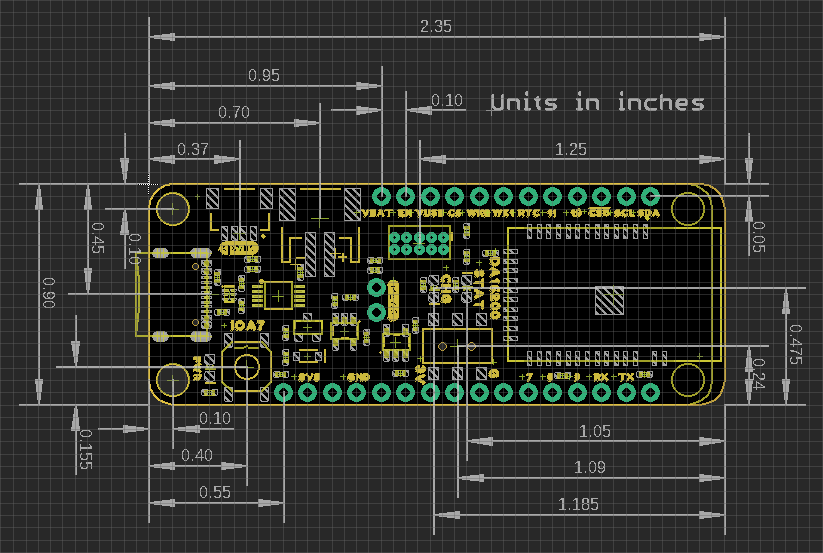
Board Dimensions
The SparkFun Thing Plus - DA16200's pin layout has a feather form factor. The board dimensions are illustrated in the drawing below.
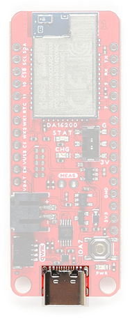
USB-C Connector
The USB connector is provided to power and interact with the board. For most users, it will be the primary programing interface for the DA16200 module.
CH340 Serial-to-UART
The CH340 allows the DA16200MOD to communicate with a computer/host device through the board's USB-C connection. This allows the board to show up as a device on the serial (or COM) port of the computer. Users will need to install the latest drivers for the computer to recognize the board (see Software Overview section).
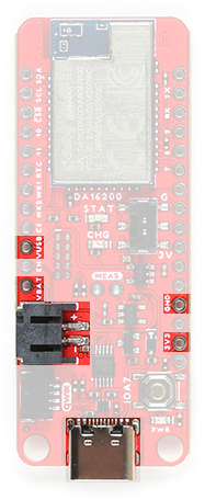
Power
The DA16200 Thing Plus only requires 3.3V to power the board. However, the simplest method to power the board is through the USB-C connector. Alternatively, the 3V3, VBAT, and VUSB pins can also be used to supply power to the board.
VUSB:- The maximum voltage for the LDOs and charge controller is 6V.
- The minimum voltage for the charge controller is 3.75V.
VBAT:- Should not be connected to anything other than a single-cell LiPo battery.
3V3:- Requires a regulated 3.3V.
- Powers the board and the Qwiic connector.
The power pins that are available on the board, are detailed below: Below, is a general summary of the power circuitry on the board:
3V3- Provides a regulated 3.3V from the USB (5V) power and/or battery connections.- Powers the DA16200MOD, status LEDs (
PWRandSTAT), and 3.3V connections of the Qwiic connector (I2C bus) and debug pins. - The 3.3V XC6222 LDO regulator can source up to 700mA.
- The output is controlled by the
ENpin on the board.
- The output is controlled by the
- Pin can also operate as an input from an external power source.
- Powers the DA16200MOD, status LEDs (
VUSB- The voltage from the USB-C connector, usually 5V.- Power source for the entire board.
- Provides power to the 3.3V voltage regulator and the battery charging circuit.
- Overides power from the battery through a P-channel MOSFET, when both are connected.
- Contains ESD protection for the USB-C connection.
- Power source for the entire board.
VBAT- The voltage from the JST battery connector; meant for single cell LiPo batteries.- Provides power to the 3.3V voltage regulator.
- The MCP73831 linear charge management controller is powered from the USB (5V) power supply.
- The charge controller is configured for 500mA (max) rate of charge to a connected battery.
GND- The common ground or the 0V reference for the voltage supplies.- Qwiic Connector - Provides a regulated 3.3V output.
For more details, users can reference the schematic and the datasheets of the individual components in the power circuitry.
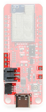
Power Status LED
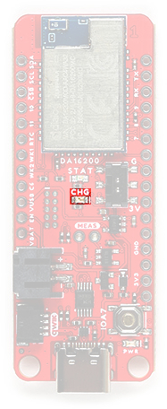
The red, POWER LED will light up once 3.3V is supplied to the board; however, for most users, it will light up when 5V is supplied through the USB connection or when a LiPo battery is connected to the JST connector.
POWER status LED indicator. (Click to enlarge) Charging Circuit
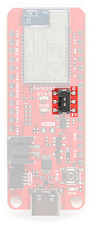
The charging circuit utilizes the MCP73831 linear charge management controller and is powered directly from the USB-C connector or VUSB. The controller is configured for a 500mA charge rate and active charging is indicated by the yellow, CHG LED. If the charge controller is shutdown or charging is complete, the CHG LED will turn off. For more information, please refer to the MCP73831 datasheet and the Indicator LEDs section below.
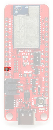
Power Control
The power source to the XC6222 is controlled by a P-channel MOSFET. In addition, the 3.3V regulated output from the XC6222 is controlled by the enable (EN) pin, broken out on the board. By default, the chip enable pin (EN) is pulled high, to enable the 3.3V output, supply voltage. To disable and shutdown the output voltage from the XC6222, the chip enable pin (EN) needs to be pulled low (i.e. shorted to ground (GND)). For more information, pleas refer to the XC6222.
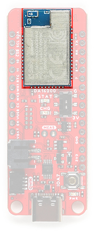
DA16200MOD WiFi Module
The DA16200MOD is an ultra low power WiFi module manufactured by Dialog (a subsidiary of Renesas). It contains a 802.11b/g/n radio (PHY), a baseband processor, a media access controller (MAC), on-chip memory, and a host networking application processor, all on a single silicon die. The system on a chip (SoC) has full offload capabilities to run the entire networking OS and TCP/IP stack on chip; therefore, an external network processor, CPU, or microcontroller are not required. The DA16200 is ideal for your next IoT project, thanks to the multiple sleep modes that allow you to take advantage of current draws as low as 0.2 - 3.5 µA.
- Operating voltage: 2.1 to 3.6 V
- Operating temperature: -40 to 85 °C
- Arm® Cortex®-M4F core w/ clock frequency of 30~160 MHz
- ROM: 256 kB
- SRAM: 512 kB
- OTP: 2 kB
- Retention SRAM: 48 kB
- WiFi processor
- IEEE 802.11b/g/n, 20MHz channel bandwidth, 2.4GHz (up to 54 Mbps)
- IEEE 802.11s Wi-Fi mesh
- WiFi security: WPA/WPA2-Enterprise/Personal, WPA2 SI, WPA3 SAE, and OWE
- Operating modes: Station, SoftAP, and Wi-Fi Direct® Modes (GO, GC, GO fixed)
- SPI flash Memory: 32 Mb (4 MB)
- On-Chip RTC (± 250 ppm)
- Three ultra-low power sleep modes
The module is Wi-Fi Alliance certified for IEEE802.11b/g/n, Wi-Fi Direct, WPS functionalities and it has been approved by many countries including the United States (FCC), Canada (IC) and China (SRRC). Using the Wi-Fi Alliance transfer policy, the Wi-Fi Certifications can be transferred without being tested again.
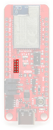
JTAG
The DA16200 Thing Plus includes JTAG PTH pins for a JTAG header, to be used with debugging probe. The JTAG pins breakout the SWD (software debug) pins to the DA16200MOD module.
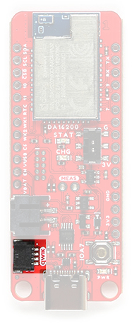
RTC Switch
On the DA16200 Thing Plus, a switch is provided to control the state of the RTC_PWR_KEY pin. The RTC_PWR_KEY of the DA16200MOD is a pin that enables the RTC block; the switch essentially controls if the DA16200MOD module is in Sleep Mode 1 and acts as an external WiFi module.
RTC swirtch on the DA16200 Thing Plus. (Click to enlarge)
| Position | Notes |
|---|---|
| G |
Sleep Mode 1 - RTC Block Disabled The DA16200MOD module should be controlled/operated by an external MCU. |
| 3V | The DA16200MOD module is in a normal active state. However, the module can still enter the Sleep Mode 2/3 states. |
Indicator LEDs
There are three indication LEDs on the DA16200 Thing Plus for:
PWR: Power (Red)CHG: Battery Charging (Yellow)STAT:GPIO A11(Blue)
Power LED
The red, PWR LED will light up once 3.3V is supplied to the board. For most users, it will light up when 5V is supplied through the USB connection and/or when a LiPo battery is attached to the JST connector.
PWR status LED indicator. (Click to enlarge) Battery Charging LED
The yellow, CHG LED will light while a battery is being charged through the charging circuit. The LED will be off when no battery is present, when the charge management controller is in standby (after the battery charging has been completed), or when the charge management controller is shutdown (thermal shutdown or when the input voltage is lower than the battery voltage). The LED will be on when the charge management controller is in the process of charging the battery. For more information, please refer to the MCP73831 datasheet.
The battery charging (
CHG) LED indicator on the DA16200 Thing Plus. (Click to enlarge)
| Charge Cycle State | STATE |
|---|---|
Shutdown
|
Off (High Z) |
| No Battery Present* | Dimmed (High Z) |
| Charge Complete – Standby | Off (H) |
| Preconditioning | On (L) |
| Constant-Current Fast Charge | On (L) |
| Constant Voltage | On (L) |
Status LED
The blue, STAT LED is typically used as a test or status LED to make sure that a board is working or for basic debugging. This indicator is connected to GPIO A11.
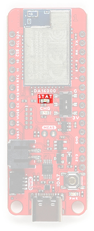
GPIO A11 on the DA16200 Thing Plus. (Click to enlarge) Reset Button
The RESET button is connected to the GPIO A7 and is used to factory reset the module; press and hold the
button for more than 5 seconds to initialize nvram data.
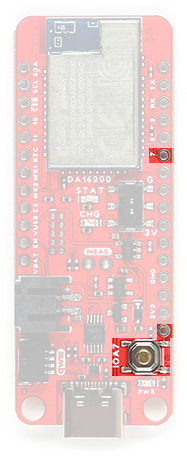
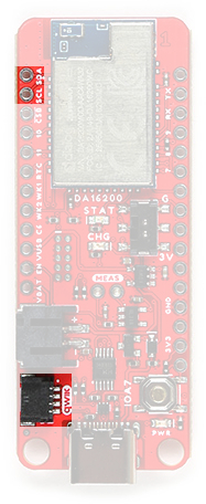
RESET button on the DA16200 Thing Plus. (Click to enlarge) I2C Bus
The I2C bus for this board utilizes the GPIO connections, detailed in the table below:
| Connection | VDD |
GND |
SCL |
SDA |
|---|---|---|---|---|
| GPIO | 3.3V | GND | GPIO A1 |
GPIO A0 |
Qwiic Connector
A Qwiic connector is provided for users to seamlessly integrate with SparkFun's Qwiic Ecosystem.
What is Qwiic?
The Qwiic system is intended a quick, hassle-free cabling/connector system for I2C devices. Qwiic is actually a play on words between "quick" and I2C or "iic".
Features of the Qwiic System
Keep your soldering iron at bay.
Cables plug easily between boards making quick work of setting up a new prototype. We currently offer three different lengths of Qwiic cables as well as a breadboard friendly cable to connect any Qwiic enabled board to anything else. Initially you may need to solder headers onto the shield to connect your platform to the Qwiic system but once that’s done it’s plug and go!

Qwiic cables connected to Spectral Sensor Breakout
Minimize your mistakes.
How many times have you swapped the SDA and SCL wires on your breadboard hoping the sensor will start working? The Qwiic connector is polarized so you know you’ll have it wired correctly, every time, from the start.
The PCB connector is part number SM04B-SRSS (Datasheet) or equivalent. The mating connector used on cables is part number SHR04V-S-B or equivalent. This is a common and low cost connector.

1mm pitch, 4-pin JST connector
Expand with ease.
It’s time to leverage the power of the I2C bus! Most Qwiic boards will have two or more connectors on them allowing multiple devices to be connected.

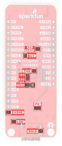
Jumpers
There are six jumpers on the DA16200 Thing Plus.
There are four adjustable solder jumpers on the mikroBUS™ carrier board labeled MEAS, BYP, 3.3V_VE and 3.3V. The table below briefly outlines their functionalities:
| Jumper Name/Label | Description | Default State |
|---|---|---|
| SHLD - USB-C Shield |
Connects the shield of the USB-C connector (metal housing) to the GND plane of the board. Users should cut the jumper when they need to isolate the shield of the USB-C connector from the board's ground plane. |
CLOSED |
| I2C - I2C Pull-Up |
Pulls the SDA/SCL lines up to 3.3V via two 2.2K Ohm resistors. Users should cut the jumper, when there are multiple devices on the I2C bus with pull up resistors. By removing the pull up resistors from the SDA and SCL lines, the strength of the pull up resistance will be reduced.
|
CLOSED |
| MEAS - Measure |
Connects the USB and battery power to the voltage regulator. Users should cut the jumper to probe the current draw into the 3.3V regulator. For help measuring current, take a look at our How to Use a Multimeter tutorial. |
CLOSED |
| LED - |
Connects the PWR LED (red) to the 3.3V power.Users should disconnect this jumper to reduce the current consumption of the board. |
CLOSED |
| CHG - |
Connects the CHG LED (YLW) to the MCP73831.Users should disconnect this jumper to reduce the current consumption of the board. |
CLOSED |
| 100/500 mA |
This jumper is used to select the charge rate to the LiPo battery from the MCP73831. Users should modify this jumper to reduce the available charrge current to the LiPo battery. |
500 mA |
| CH340 |
Connects the CH340 Serial-to-UART chip to 3.3V power. Users should disconnect this jumper to reduce the current consumption of the board. |
CLOSED |
| RST - Reset |
Connects GPIO A7 to the IOA7 button and the RST PTH pin.Users should cut the jumper to disconnect the GPIO pin from the pull up resistor and isolaate the GPIO from the IOA7 button and the RST PTH pin.
|
CLOSED |
| DA MEAS - DA16200MOD |
Connects 3.3V to the DA16200MOD module. Users should cut this jumper to measure the current directly to the DA16200MOD. Users can make their measurements through the jumper pads. |
CLOSED |
Note: When modifying these jumpers, be careful to avoid cutting nearby traces. Although not usually an issue, we thought to mention that this board is also a 4-layer PCB, so be careful not to cut the jumper too deep.

Traces (blue) near the jumpers on the DA16200 Thing Plus. (Click to enlarge)