CryptoCape Hookup Guide
This Tutorial is Retired!
This tutorial covers concepts or technologies that are no longer current. It's still here for you to read and enjoy, but may not be as useful as our newest tutorials.
 jbdatko,
  CaseyTheRobot
Atmega 328
The ATmega328p operates at 3.3V and 8Mhz, just like the Arduino Pro Mini. It is loaded with the Arduino Pro Mini 3.3V bootloader and contains a basic test sketch from the factory. There are two ways to upload sketches to this chip: Using an ISP programmer or from the BeagleBone.
Using an external programmer
The Pocket AVR Programmer will work to program the ATmega. You'll need to populate the ISP headers with some 0.1" male headers. When you connect the Pocket Programmer, be sure to select "No Power" because the CryptoCape receives 3.3V power from the BeagleBone. While most of the chips on this board are 5V friendly, the oscillator for the TPM is not. You can then use the USBTiny programmer option from the Arduino IDE.
Using the BeagleBone
Since the ATmega is tied to the BeagleBone's UART4, the BeagleBone can flash sketches up to the ATmega. If you want a detailed description of how this works, check out the May 2014 cover article of Linux Journal. You'll not only see how to program the ATmega, you'll read how the device tree works in gory details.
For those that just want to upload sketches quickly, clone the following repository from your BeagleBone:
git clone https://github.com/jbdatko/BBB_ATmega328P_flasher.git
In that repository, there is an upload.sh script, which is invoked as follows:
sudo ./upload.sh Blink.cpp.hex
Replace Blink.cpp.hex with the hex file you want to flash. How do you get this hex file? In your Arduino IDE, go to "Preferences" then "Show verbose output during compilation." When you "verify" your sketch, the output window will tell you where the hex file lives. Download this to the BeagleBone with sftp or something similar.
Installing the Jumpers
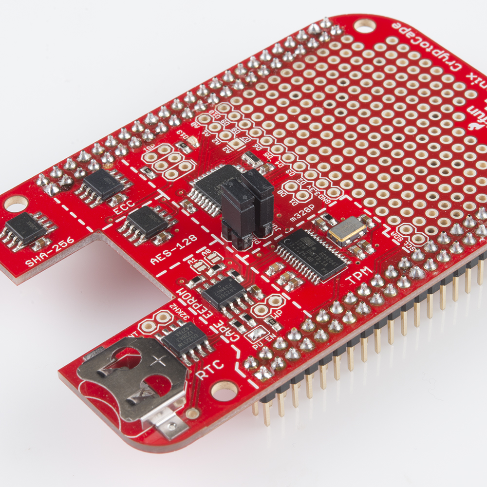
To flash the ATmega from the Beagle, you must physically attach jumpers to the "Program Jumper" pads. You should solder 0.1" male headers to these pads. The spacing between these jumpers is purposely oddly spaced to prevent you from attaching the jumpers in the wrong direction. Without the jumpers, you can't upload sketches from the Beagle.
This is a security feature. We wouldn't want some malware changing the firmware on the ATmega, now would we?
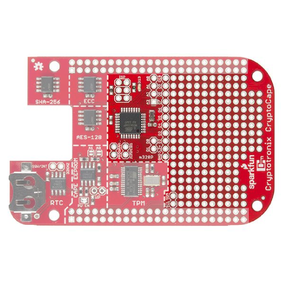
Breakout Pads
The CryptoCape breaks out most of the ATmega signals to surrounding pads. There is even a green LED which is compatible with the typical "Blink" sketch, so you can upload that example to make sure everything is working. Not all the Arduino signals are broken out, but the ones that are available on the CryptoCape are listed here:
- GND
- 3.3V
- D0 - D10
- D13 with LED
- A0 - A13
The serial UART between the BeagleBone and the ATmega can be split. If you don't put the jumpers on, the serial line will not be connected, and the BeagleBone can use the "upstream" side of the serial lines while the ATmega can use the "downstream." This might be useful if you have two serial devices and you want the BeagleBone to talk to one of them and the ATmega to the other, without mixing the signals.
I2C
The ATmega is connected to the same I2C bus as all of the other chips. This means you can join the bus as an I2C slave with Wire.begin(address) and communicate with the Beagle over I2C. Just be sure to pick an address not already in use. We recommend 0x42, because it's the answer to life, the universe, and everything. But if you attached the HMC6352, you'll need a new address since that is also 0x42.
This blog post contains a detailed overview of using I2C on the BeagleBone Black.