Boss Alarm
 AGlass0fMilk
Making the Owl Transceiver
Circuit Operation
Here's the circuit schematic for the owl:
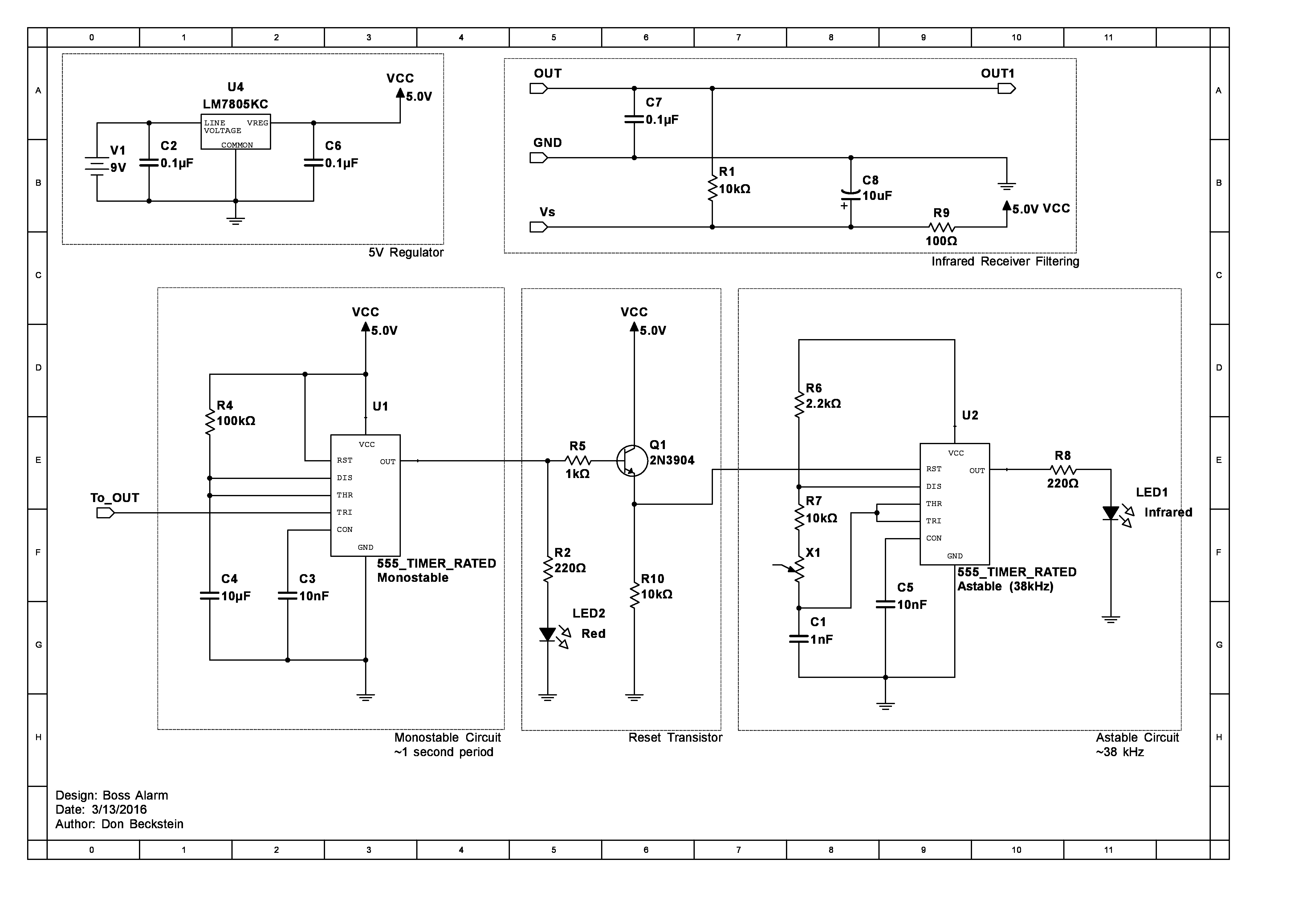
The circuit for the owl may look really complicated but it's not! The owl transceiver operates in a way similar to the squirrel transmitter. Only instead of having one 555 timer circuit, the owl has TWO! Let's go through it step by step.
The owl has a 555 timer operating in monostable mode and another operating in astable mode. The IR Receiver Diode is an active low device. This means that, when it receives a signal, the output pin is pulled low. This works great with our 555 timer since the trigger pin needs to be pulled low to activate the monostable circuit.
The monostable circuit is designed to hold the output high for approximately 1 second (this timing isn't crucial) when triggered by the IR Receiver.
The next part of the circuit is our reset transistor. There are two current-limiting resistors (1kΩ for the base, 220Ω for the Red eye LED) and a 10kΩ pull-down resistor on the transistor's emitter.
Notice that the emitter is also connected to the reset pin of the second 555 timer. In most astable applications, you tie the reset pin to the supply voltage so the chip is always on. However, in this project we only want the owl to send a signal to the computer when someone walks by.
In this configuration, when the output of the first 555 is low, the transistor will be off. The pull-down resistor makes sure the voltage seen by the second 555 timer's reset pin is around 0V, keeping it off. When the circuit is triggered, the red LED and the transistor turn on. Since the transistor is conducting, the voltage at the emitter becomes high enough to enable the second 555 timer for about 1 second.
The second 555 timer is designed to operate in astable mode at 38kHz just like the circuit in the squirrel. This sends another infrared signal to your computer telling it that someone walked by!
The additional circuits shown in the schematic are the 5V regulator circuit and the infrared receiver filtering circuit. The regulator simply takes the 9 volts from the battery and outputs a stable 5V source that plays nicely with our infrared receiver. The filtering circuit has a couple capacitors that help stabilize the output of the receiver and a pull-up resistor to keep the output high when the receiver is off.
Soldering Time!
The parts you need for this component of the project are:
- 100Ω, 220Ω (x2), 1kΩ, 2.2kΩ, 10kΩ (x3), and 100kΩ Resistors
- 10kΩ potentiometer
- 1nF, 10nF (x2), 0.1μF (x3), and 10μF (x2) capacitors
- Infrared LED
- Red LED
- Infrared Receiver
- 555 timer (x2)
- 2N3904 NPN Transistor
- L7805 Regulator
- 9V Battery Connector
- Snapable Protoboard
- Heatshrink Tubing
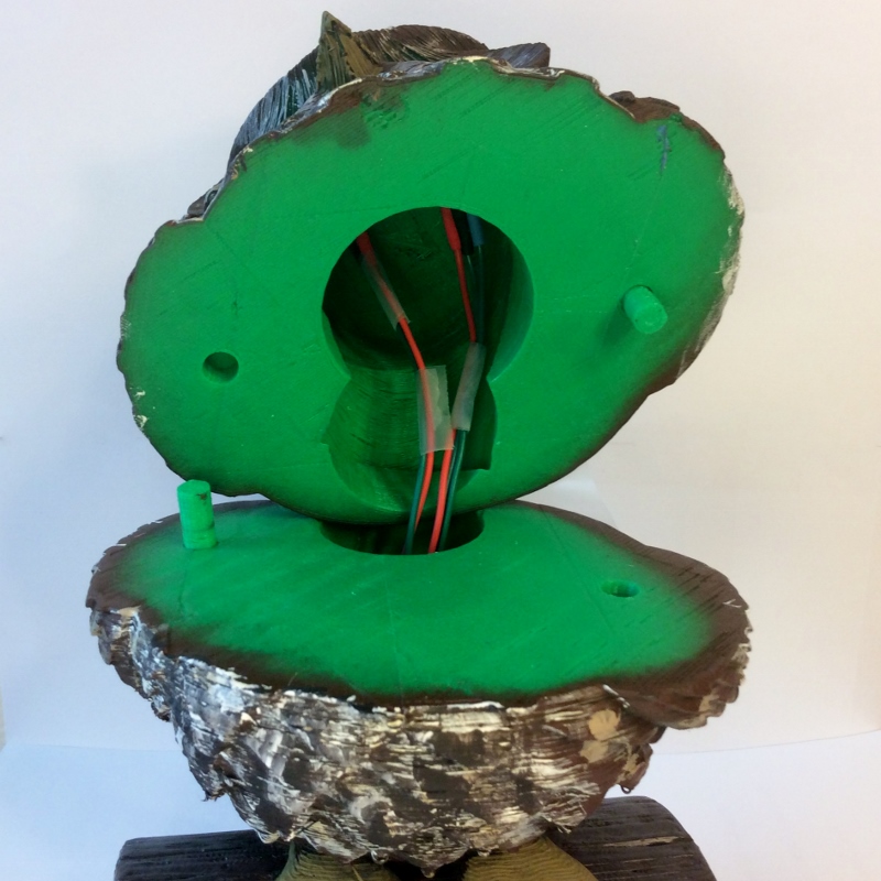
Build the circuit according to the included schematic. Make sure not to solder the red and infrared LEDs or the infrared receiver. Just like with the squirrel, solder on some long wires to these, and cover the connections with shrink tubing.

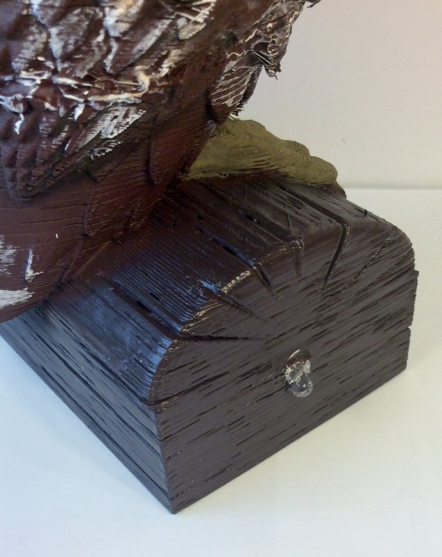
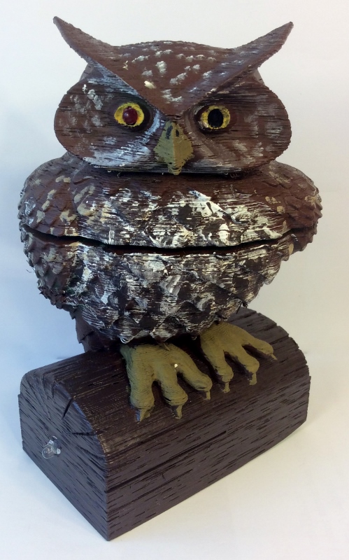
Paint the owl however you want; I went with a classic brown woodland owl. Again, you may need to drill out the mounting holes to get the parts to fit. It's best to do this before painting the models to avoid scratching the paint off.
When your model is prepped, you can install the components. The infrared LED is mounted in the hole on the side of the log. The Red LED goes in either eye of the owl. The IR receiver goes in the other eye of the owl. Solder the components to the board, and it should be all set!