Beginner Parts Kit Identification Guide
 jimblom,
  bboyho
Examples In Action!
Below we'll tackle a few common circuits that use components from the Parts Kit. Hopefully, they'll spring ideas for new projects. Unfortunately, the parts kit doesn't have quite everything you'll need to complete these quick circuits, but I'll link any additional parts you'll need. A common theme of all of these projects is they're breadboard based, if you're looking for an addition to your parts catalog, and you don't already have one, a breadboard is a great place to start. You may also want to add a resistor kit, power supply, and adapter to your collection as well.
Example 1: A Simple Regulated Power Supply
We can use the included voltage regulators, 1N4001 diode, and capacitors to create a regulated power supply.
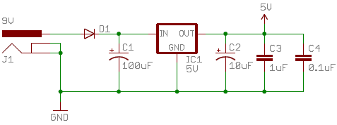
From the barrel jack connector, we first run power into the 1N4001 diode. Because the diode conducts current only in the positive direction, this adds reverse power protection to the circuit. If someone were crazy enough to connect the barrel jack backwards, the diode would protect the C1 capacitor and the regulator from being subjected to -9V (remember our talk about blowing up electrolytics?).
You'll notice caps thrown about everywhere around the circuit; these are all decoupling caps, used to limit the noise in the power supply. When adding decoupling caps, it's always beneficial to add a range of values, and even different types of capacitors. Depending on the desired output voltage, you can use either the 3.3V or 5V regulator. That's it, you've got a nice, happy, regulated supply; the first and most important step in project design. If you want to take this design a step further, you could add a resistor and an LED, to act as a power indicator. To toggle power, try adding the switch between the diode and voltage regulator.
Example 2: Controlling an LED with Light
Sometimes the simplest circuits can be the most enthralling, awesome things ever. That's the case with this circuit, all you need is a power supply, a photoresistor, and an LED.
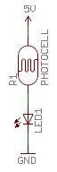
The photoresistor limits the current that flows through the LED, thus controlling the brightness. See if you can turn the LED completely off; I sure couldn't. Then see how bright you can get the LED, as it plays the part of Icarus soaring ever-closer to it's light source.
If you're like me, that circuit's a little counter-intuitive. The LED should turn on when it's dark, off when it's light; an automatic nightlight. The addition of a transistor, and a couple resistors solves that problem:
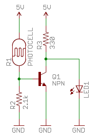
In this circuit the transistor acts as an inverter. If the resistance of the photocell is low, meaning it's bright out, the transistor is on, and the LED is pulled towards ground. If the photocell's resistance is high, and it's dark out, the transistor turns off and the LED is turned on. That's the magic of transistors! You may need to play with the R2 resistor to adjust the sensitivity of your nightlight.
Example 3: A Single-Digit 7-Segment Display
There's not a whole lot you can say with one character, but you could get a little creative and use it with a switch, to display multiple characters on a single display. Say you have a special affinity for the number 13, you could use the Mini Power Switch in addition to a 330Ω resistor and the Red 7-Segment Display to (sort-of) display it.
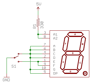
The resistor is added to limit the current going into all of the segments; you don't want to blow up your pretty red LEDs. Now flip the switch really quickly and visualize that 13! Maybe you could add a potentiometer, allowing you to dim the LED.
Example 4: Blinking an LED at 1 Hz
Continuing on the premise that blinky things rule, let's use the 555 timer to control an LED that keeps a beat. Again you'll need a few resistors, in addition to a 555, 10uF capacitor, 10nF capacitor, and an LED.
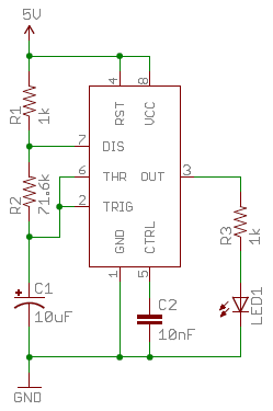
Blinkies! The 555 timer is running in astable mode, which means it continuously outputs square waves at a near 50% duty cycle. You can adjust the value of R2 to speed up, or slow down the blinky. Try replacing R2 with a potentiometer.
Hopefully these examples provide you with a good idea of what kind of magic you've got in that parts box. Now it's time to create something amazing; and when you do, let us know about it!