AST-CAN485 I/O Shield (24V) Hookup Guide
 Alex the Giant, Ell C, JamesBM
 Introduction
The AST-CAN485 I/O Shield (24) is an Arduino shield that will allow the user to interface the AST-CAN485 Dev Board with 24V inputs and outputs, which expands its usefulness into industrial systems.
SparkFun AST-CAN485 I/O Shield (24V)
DEV-14598Required Materials
To follow along with this tutorial, you will need the following materials. You may not need everything though depending on what you have. Add it to your cart, read through the guide, and adjust the cart as necessary.
Tools
Depending on your setup, you will need a soldering iron, solder, and general soldering accessories to solder pins to the AST-CAN485. You will also need a flat head and wire strippers to connect wires to the screw terminals.


Wire Strippers - 20-30AWG
TOL-14763Suggested Reading
We recommend checking out the AST-CAN485 Hookup Guide to get started with the board. Depending on your setup, you may need to install custom libraries and board add-ons.
AST-CAN485 Hookup Guide
Also, if you aren’t familiar with the following concepts, we recommend checking out these tutorials before continuing.
Working with Wire
Hardware Overview
Input Power
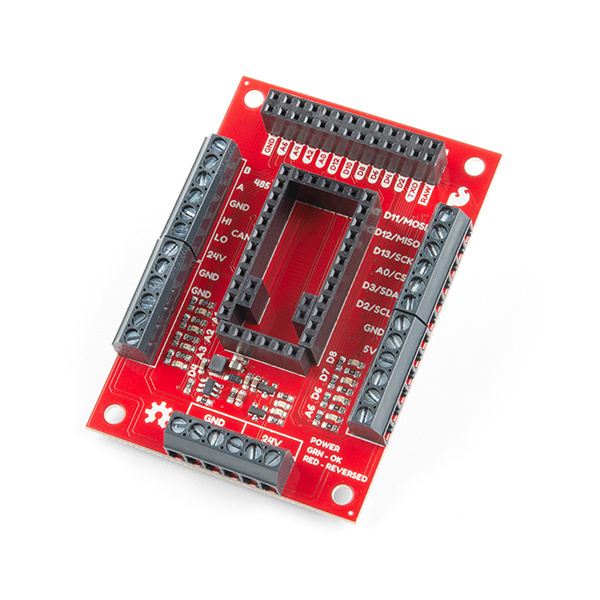
The AST-CAN485 I/O Shield provides a socket to break out all of the IO of the AST-CAN485 board. To make a secure connection to your industrial equipment, screw terminals come pre-soldered to the board to get you up and running in no time. The AST-CAN485 I/O Shield is designed to work in the industrial 24V environment, but has a wide supply input range of 7-24V. The board comes with input reverse voltage protection with a green and red status LEDs (green means power is connected properly, and red indicates reversed power, and blocks power to the rest of the board.

24 I/O Pins
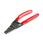
At your disposal are four 24V input channels with LEDs to indicate the input logic level, along with an additional four 24V output channels with matching indicator LEDs.
RS-485 and CAN
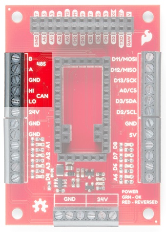
Which do you prefer to use for your communication standard: RS-485 or CAN? Well it doesn't matter because as the name indicates, the CAN485 board will handle them both, and they're both broken out to the secure screw terminals as well!
SPI and I2C
If SPI and I2C are more in your wheelhouse, the CAN485 board breaks those out to screw terminals well, but you are limited to 5V logic.
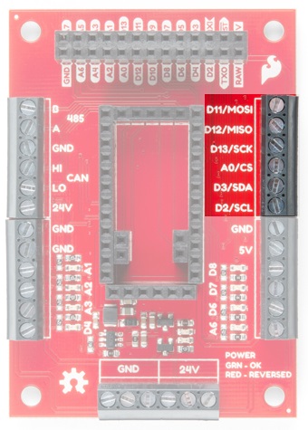
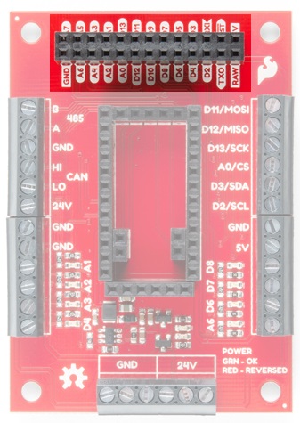
AST-CAN485 Pins
All of the 5V logic level pins of the AST-CAN485 board are also broken out with an easy to read 2x13 pin header.
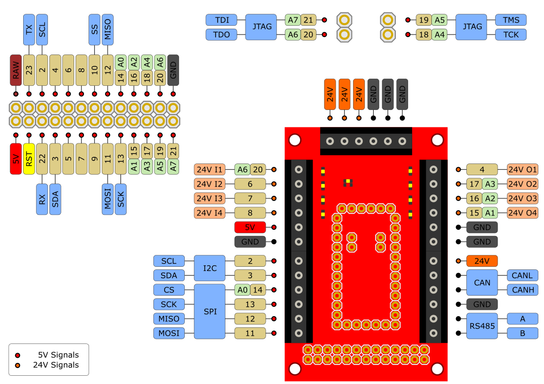
Pinouts
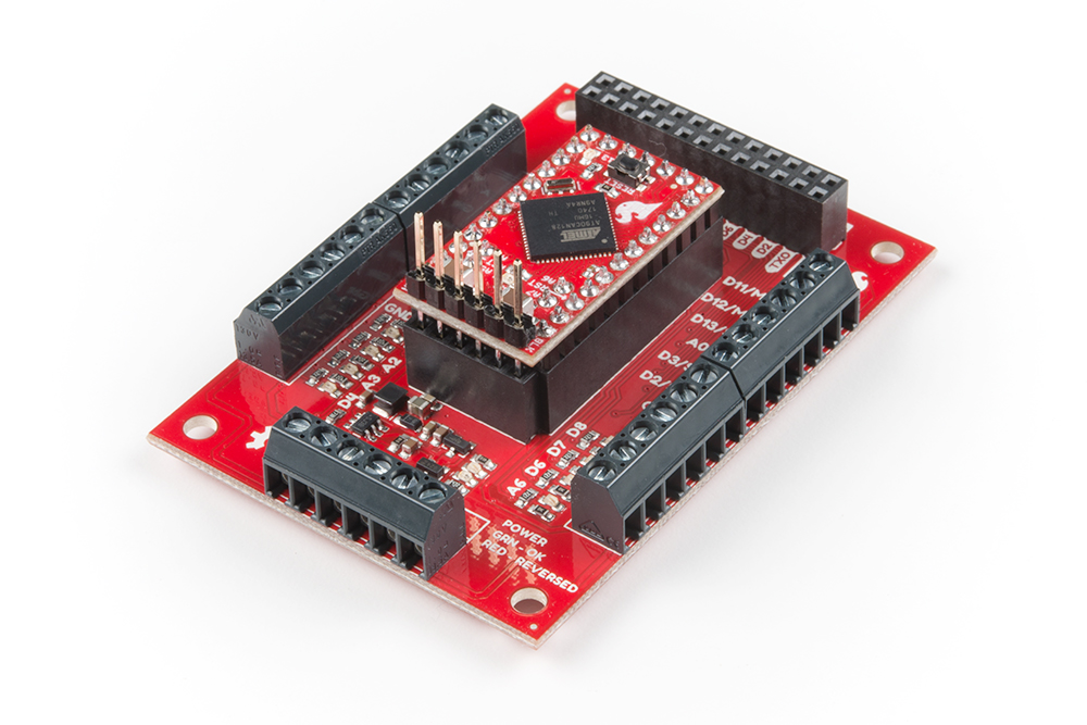
Hardware Hookup
The AST-CAN485 I/O shield comes with female headers pre-soldered. Insert the CAN485 as shown with the FTDI header close to the input power pins:
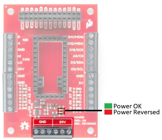
Powering The Shield
The shield requires 24V power in order to function correctly. This can be supplied on any of the power terminals as shown below. Additional terminals are provided to allow powering of external devices.
There is reverse voltage protection on the 24V power terminals. The power status LED will show green for correctly wired power. If wired incorrectly, the LED will be red.
An integrated power supply regulates the 24V input power down to 5V which is used to provide power to the inserted CAN485 board. This 5V supply is also broken out to the terminals as shown.
Software Setup and Programming
This board is a shield for the AST-CAN485 development board and is not programmed directly. There is a library for the CAN485 which enables some board features and contains some examples. It can be downloaded from the GitHub Repo or by clicking the button below to manually install.
JTAG
One limitation of the shield is that JTAG debugging and Input 24V I1 cannot be used at the same time. Input V24 I1 is connected to pin A6 on the CAN485, this pin is also used for JTAG debugging. In order to use that input channel, JTAG debugging must be disabled. This is done automatically when calling the board initialization function provided by the library.
Examples
The library also includes several examples which demonstrate the use of the board. After installing the library, open up one the examples listed in the folder File > Examples > AST_V241O through the Arduino IDE. Select the CAN485 as the board, the COM port that it enumerated on, and hit upload to test.
- BlinkOneOutput -- Turn 24V O1 (D4) on and off.
- CycleOutputs -- Toggle all pins connected to the 24V output.
- ReadInputs -- Read all 24V input pins and print to serial monitor at a baud rate of
1000000. - ReadInputsToOutputs -- Read the inputs and toggle outputs.
Resources and Going Further
For more information, refer to the links below:
AST-CAN485 I/O Shield (24V)
AST-CAN485 Development Board
Need some inspiration for your next project? Check out some of these related tutorials:
OBD II UART Hookup Guide
CAN-BUS Shield Hookup Guide
Getting Started with OBD-II
Or dig in further with According to Pete for more information about RS485.