Adding a Timed Button to a Project
 Sarah Al-Mutlaq
Introduction
In this tutorial you will learn how to add an on button that will provide power to your project for an amount of time and then turn off again. We will be using a Solid State Relay (SSR) to deal with AC (alternating current) voltages like what you would see coming out of your wall at your house.
Required Materials
If you would like to follow along with this tutorial, you will need the following:
Suggested Readings
Before getting started, you may find some of the concepts below helpful.
Why Have a Timed Power Button?
Saving energy is always a good thing, but some projects have sensitive components that need a bit of a break and would last much longer if they weren't on all the time.
Some interactive projects should not stay powered on indefinitely. Parts of LEDs (especially RGB LEDs) can burn out, systems can lock up. In SparkFun’s new retail space we have dozens of demos that could benefit from a big button that allows the user to power up the project for 5 minutes then powers down until the next customer walks by. The first project to get this attention is our classic Picture Frame Tetris. We hate leaving this on for 24 hours a day because it wastes power, it doesn’t have a good screen saver mode, and we are worried that the LEDs may burn out over time. This button was designed for that, a simple way to provide power to a project for a short time, only when needed.
Getting Started and Uploading Code
Since the project to which I am adding a timer uses DC (direct current), I could have easily added the timer to regulate the DC voltage using just a simple DC relay switch. Most projects in your home will be running off power from the wall, so this tutorial will focus more on how to regulate the AC voltage and current.
We will start with uploading the code. For this project, I have chosen a 5V Pro Mini. To Program a Pro Mini, you'll need a 5V FTDI Breakout. If your system is using 3.3V instead of 5V, we also have a 3.3V Pro Mini, and 3.3V FTDI Breakout to match.
To connect the Pro Mini to the FTDI Breakout, all you need to do is solder some right-angle male headers onto the FTDI inputs on the Pro Mini.
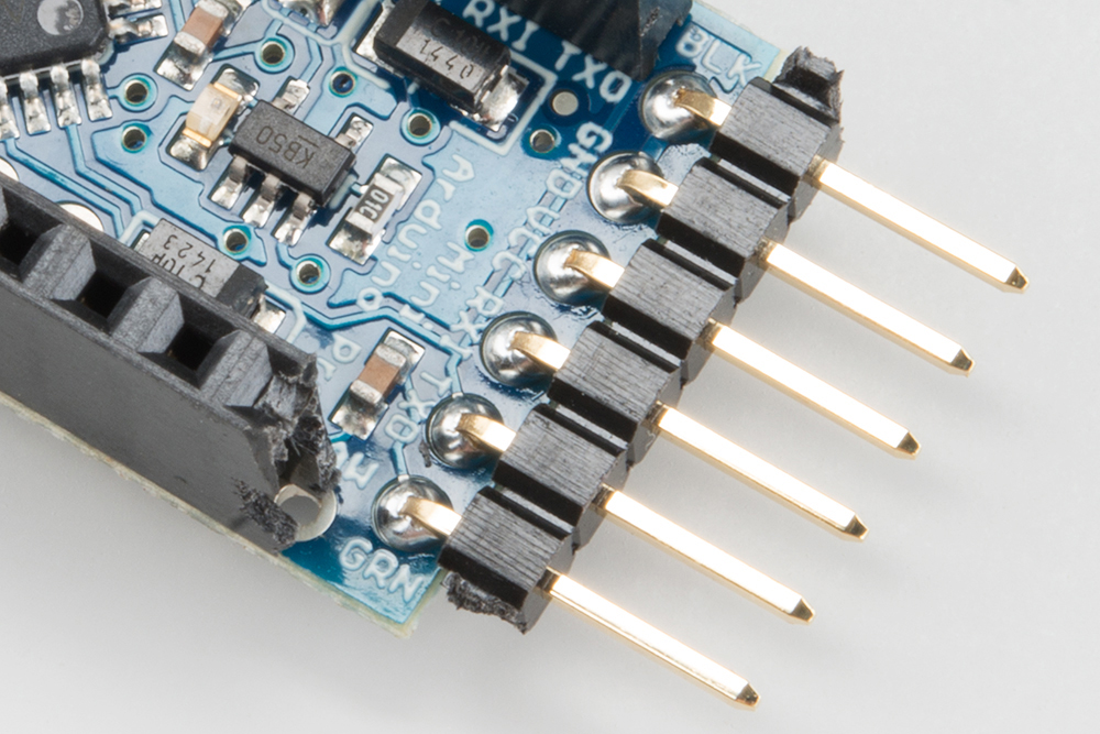
Once you have the FTDI breakout plugged into the Pro Mini, you can use a USB to Mini-B Cable to plug it right into your computer.
Open up the Arduino IDE, and upload the example code to your Pro Mini (for specific info on what the code is doing take a look at the comments in the code):
language:c
 /*
SparkFun simple code for running an On timer
for power from a button push
By: Sarah Al-Mutlaq
7/9/15
*/

int startButton = 13; //pin recieving info from start button
int controlPin = 4;   //pin we will use to contol power

unsigned long timerCount = 0; // variable to hold our timer info


void setup()
{
  pinMode(startButton, INPUT); //set pin as recieving info
  pinMode(controlPin, OUTPUT); //set pin as giving info
  digitalWrite(controlPin, LOW); //starting the control to project power as off
}

void loop()
{
  if (digitalRead(startButton) == HIGH)
    { //if the start button has be pushed
     timerCount = 5 * 60 * 10; //set timer to approximately 5 mins
     //(5 mins *  60 sec * 10 * 1 deciseconds)
     //this is set up to restart the timer whenever the start
     //button is pushed
     //not extremely exact since that is not what I needed for this project
     //if you are looking for something more exact, look into
     //SimpleTimer() Arduino funtions and libraries:
     //http://playground.arduino.cc/Code/SimpleTimer#F_restartTimer
    }
  if (timerCount != 0)
   { //if the count down timer is still running
     digitalWrite(controlPin, HIGH);
     //tell the control pin to provide power to the project
     timerCount = timerCount - 1;
     //count down of a decisecond (0.1 sec)
     delay(100);
     //delay for timercCount refrence of a decisecond
   }
   else { //if the timer has run out
     digitalWrite(controlPin, LOW);
     //tell the control pin to stop power to the project
   }
}
Hardware Hookup
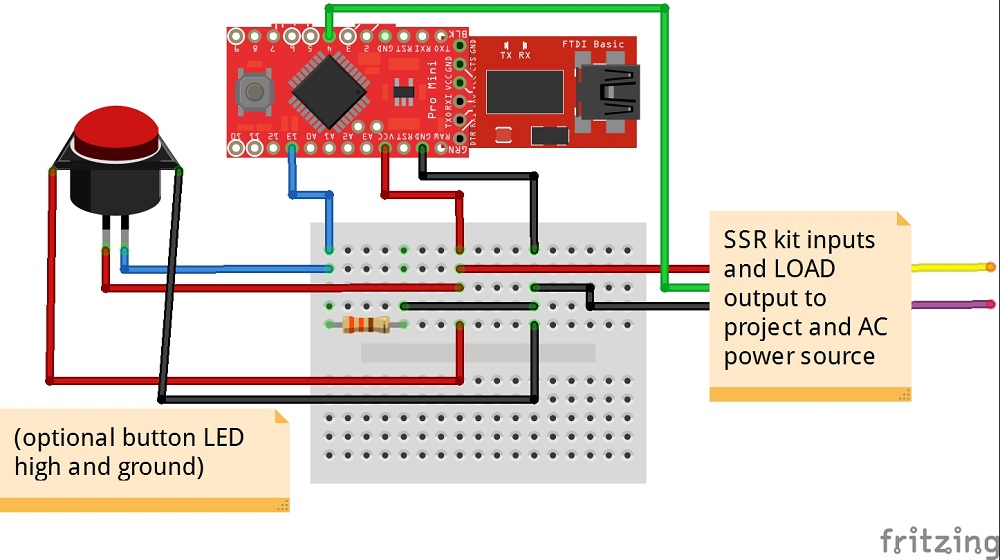
As you can see in the code, we will be hooking up the button to pin 13 of the Pro Mini (this can be changed to any pin in the code) and pin 4, as well as 5V high and Ground to our SSR kit (also can be changed in the code). To connect the Pro Mini, you can either directly solder wires onto the pins, 5V, and ground. Or, you can solder on female headers, and plug wires into those.

The SSR kit does not come with all of its parts soldered on, so you will need to assemble it.
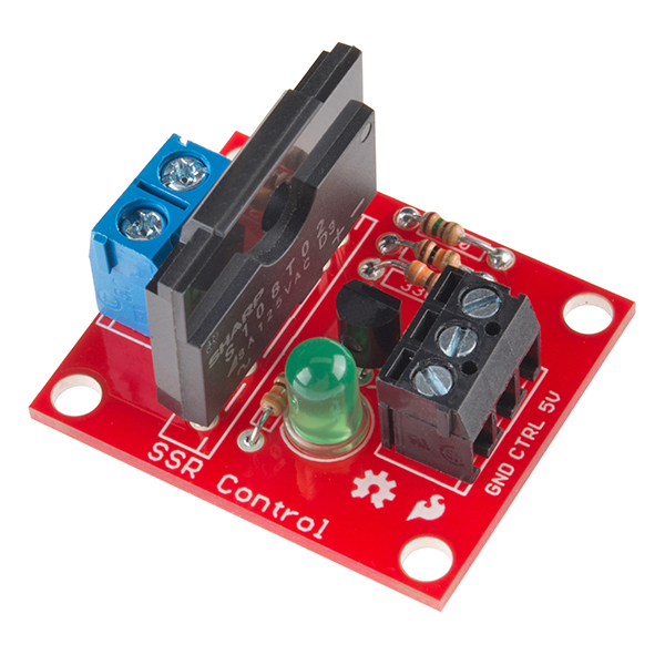
This solid state relay kit is rated for a max of 125VAC at 8A, so, for a small-medium size project, this is a fine option. However if your project is going to be pulling more current or voltage you might want to look into a full blown Solid State Relay (SSR), this one can handle 380VAC and 40A!
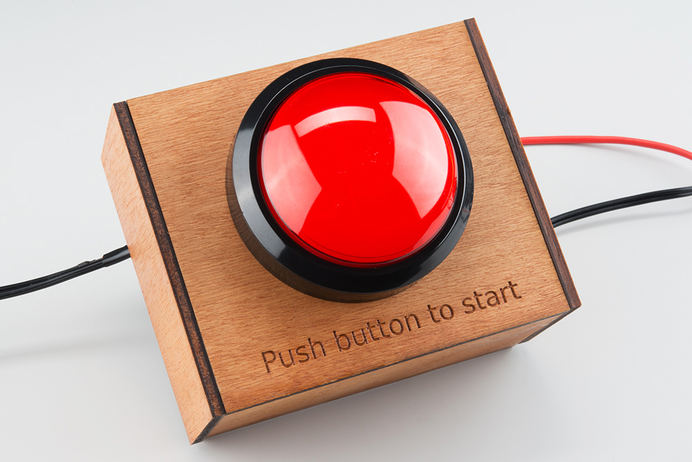
Since I used a Big Dome Pushbutton, I will also be hooking up the LED inside to Vcc and Ground. The code recognizes that the button is pushed when the pin goes high. This means the button will be pulled low and only go high when the button is pushed (meaning 5V will be connected to the pin the button connects when it is pushed).
Last, the load pins on the SSR kit will be hooked up to one of the wires that are going from your project to the AC power supply (usually the wall).

To protect the project and make sure that nothing is going to short, I recommend covering everything with electrical tape or Heat Shrink. I also added a fair amount of hot glue to this project to protect all the connections and keep everything in place.
Once everything is hooked up and in place, you can plug your Pro Mini (through the FTDI Breakout) into the wall with a 5V adapter, plug in your connected project, and there you have it! A timed on button for your project!
I cut a few pieces of plywood and glued them together to form a little housing for the button.
Resources and Going Further
Ready for your next project? Check out some of our other awesome tutorials: