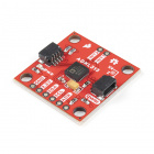
Accelerometer Basics
What is an Accelerometer?
Accelerometers are devices that measure acceleration, which is the rate of change of the velocity of an object. They measure in meters per second squared (m/s2) or in G-forces (g). A single G-force for us here on planet Earth is equivalent to 9.8 m/s2, but this does vary slightly with elevation (and will be a different value on different planets due to variations in gravitational pull). Accelerometers are useful for sensing vibrations in systems or for orientation applications.
Suggested Reading
If you are unfamiliar with any of the topics below, you may want to read up on those before moving ahead with accelerometers.
Serial Peripheral Interface (SPI)
Analog to Digital Conversion
Pulse Width Modulation
Logic Levels
I2C
How an Accelerometer Works
Accelerometers are electromechanical devices that sense either static or dynamic forces of acceleration. Static forces include gravity, while dynamic forces can include vibrations and movement.
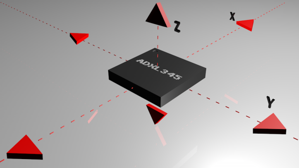
Accelerometers can measure acceleration on one, two, or three axes. 3-axis units are becoming more common as the cost of development for them decreases.
Generally, accelerometers contain capacitive plates internally. Some of these are fixed, while others are attached to minuscule springs that move internally as acceleration forces act upon the sensor. As these plates move in relation to each other, the capacitance between them changes. From these changes in capacitance, the acceleration can be determined.
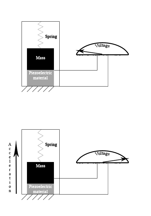
Other accelerometers can be centered around piezoelectric materials. These tiny crystal structures output electrical charge when placed under mechanical stress ( e.g. acceleration).
How to Connect to an Accelerometer
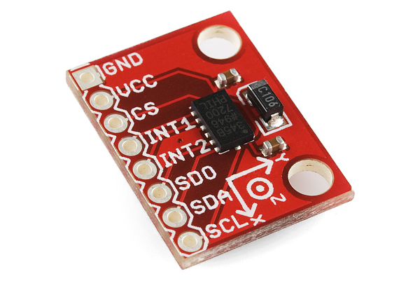
For most accelerometers, the basic connections required for operation are power and the communication lines. As always, read the datasheet to ensure proper connections are made.
Communication Interface
Accelerometers will communicate over an analog, digital, or pulse-width modulated connection interface.
Analog - Accelerometers with an analog interface show accelerations through varying voltage levels. These values generally fluctuate between ground and the supply voltage level. An ADC on a microcontroller can then be used to read this value. These are generally less expensive than digital accelerometers.
Digital - Accelerometers with a digital interface can either communicate over SPI or I2C communication protocols. These tend to have more functionality and be less susceptible to noise than analog accelerometers.
Pulse-Width Modulation (PWM) - Accelerometers that output data over pulse-width modulation (PWM) output square waves with a known period, but a duty cycle that varies with changes in acceleration.
Power
Accelerometers are generally low-power devices. The required current typically falls in the micro (µ) or milli-amp range, with a supply voltage of 5V or less. The current consumption can vary depending on the settings (e.g., power saving mode versus standard operating mode). These different modes can make accelerometers well suited for battery powered applications.
Make sure that proper logic levels are matched, especially with the digital interfaces.
How to Select an Accelerometer
When choosing which accelerometer to use, several features are important to consider including power requirements and communication interfaces as discussed previously. Additional features for consideration are below.
Range
Most accelerometers will have a selectable range of forces they can measure. These ranges can vary from ±1g up to ±250g. Typically, the smaller the range, the more sensitive the readings will be from the accelerometer. For example, to measure small vibrations on a tabletop, using a small-range accelerometer will provide more detailed data than using a 250g range (which is more suited for rockets).
Additional Features
Some accelerometers include features such as tap detection (useful for low-power applications), free-fall detection (used for Active Hard Drive Protection), temperature compensation (to increase accuracy in dead reckoning situations ) and 0-g range sensing, which are other features to take into consideration when purchasing an accelerometer. The need for these types of features on the accelerometer will be determined by the application in which the accelerometer is incorporated.
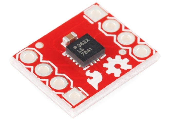
There are also IMUs (Inertial Measurement Units) available, which can include accelerometers, gyroscopes and even, occasionally, magnetometers into a single IC package or board. Some examples of this include the MPU6050 and MPU9150. These are commonly used in motion tracking applications and UAV guidance systems, where location and orientation of an object is important.
Purchasing an Accelerometer
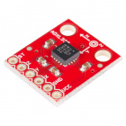
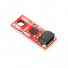
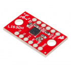
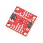
Now that you've learned the abc's of the x's, y's, and z's, take a look at our recommended accelerometers from the SparkFun catalog
Our Recommendations:
For a more in-depth look at choosing an accelerometer, take a look at our buying guide to find the right fit for your project.
Resources and Going Further
You should now have all the basic tools and skills required to implement an accelerometer in your own project.
Please check out the following links, to learn more about accelerometers:
