9DoF Razor IMU M0 Hookup Guide
 jimblom
 Introduction
The SparkFun 9DoF Razor IMU M0 combines a SAMD21 microprocessor with an MPU-9250 9DoF (nine degrees of freedom) sensor to create a tiny, re-programmable, multi-purpose inertial measurement unit (IMU). It can be programmed to monitor and log motion, transmit Euler angles over a serial port, or to even act as a step-counting pedometer.
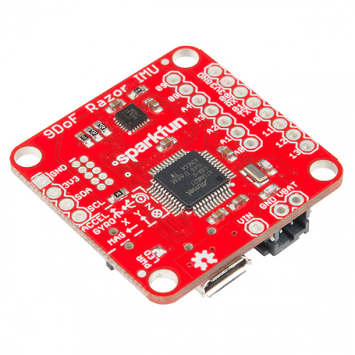
The 9DoF Razor's MPU-9250 features three, three-axis sensors -- an accelerometer, gyroscope, and magnetometer -- which gives it the ability to sense linear acceleration, angular rotation velocity, and magnetic field vector's. The on-board microprocessor -- Atmel's SAMD21G18A -- is an Arduino-compatible, 32-bit ARM Cortex-M0+ microcontroller also featured on the Arduino Zero and SAMD21 Mini Breakout boards.
In addition to pair of IC's, the 9DoF Razor IMU includes a µSD card socket, LiPo battery charger, power-control switch, and a host of I/O break-outs for project expansion. It comes pre-programmed with example firmware and an Arduino-compatible bootloader, so you can customize the firmware and flash new code over a USB connection.
Covered In This Tutorial
This tutorial serves as both a primary documentation source and getting started guide for the SparkFun 9DoF Razor IMU M0. The first couple of sections document hardware and firmware features of the board, while the latter half of the tutorial demonstrates how to use the Arduino IDE and our MPU-9250 Arduino library to re-program the Razor IMU to your specific needs.
Bill of Materials
The 9DoF Razor IMU M0 comes populated with just about everything you could need to take advantage of the MPU-9250 9DoF sensor. There are just a handful of items -- most of which you probably already have in your toolbox -- you may need in addition to the board.
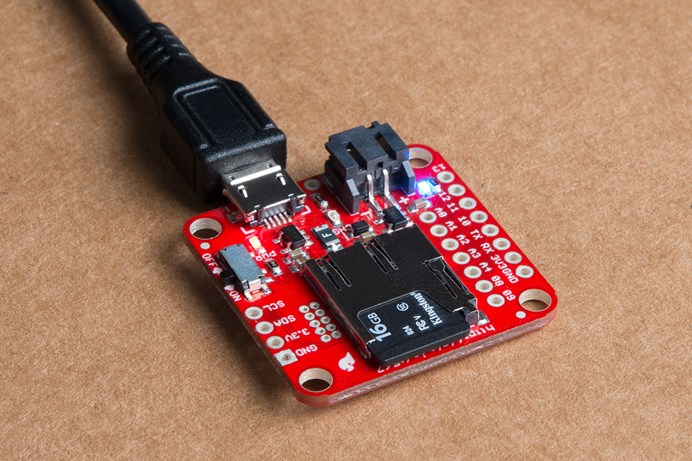
A micro-B USB cable can be used to both power and re-program the Razor. But, if you truly want to make the board mobile, you'll need a single-cell Lithium-polymer (LiPo) battery, which can be recharged by plugging the 9DoF Razor into a USB supply. Additionally, if you want to log data, the 9DoF Razor IMU's µSD socket supports any µSD card.


Finally, you may need soldering tools and headers or wire, if you want to take advantage of the 9DoF Razor IMU's I/O and power breakouts.


Suggested Reading
Feel free to jump right into using and developing on the 9DoF Razor IMU M0 -- we've tried to make the board as easy to use regardless of you electronics experience level. If you'd like to do some pre-reading, though, here are a few tutorials we might recommend:
Gyroscope
SAMD21 Mini/Dev Breakout Hookup Guide
Hardware Overview
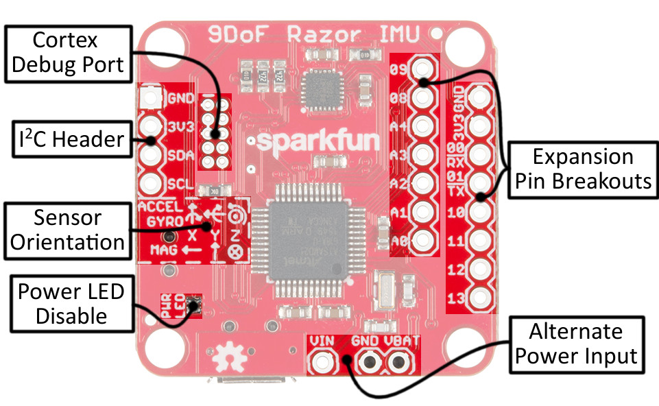
The 9DoF Razor IMU M0 is a double-sided assembly, which means there's a lot going on on both sides of the board. Here's an overview of what we'll call the "top" of the board.
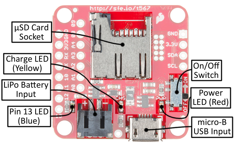
While the bottom of the board includes the various connectors, power control switch, and LEDs.
Open Source Hardware! The 9DoF Razor IMU M0 is an open-source hardware design. Feel free to download the schematic (PDF), Eagle files (PCB design), or browse the design's history in our GitHub repository.
Powering the 9DoF Razor IMU M0
The Razor IMU is designed to work with either a USB power source or a single-cell Lithium-polymer (LiPo) battery. The black, PH-series JST connector should mate with any of the similar LiPo batteries in our catalog -- just make sure they're single cell (nominal voltage 3.7-4.2V).
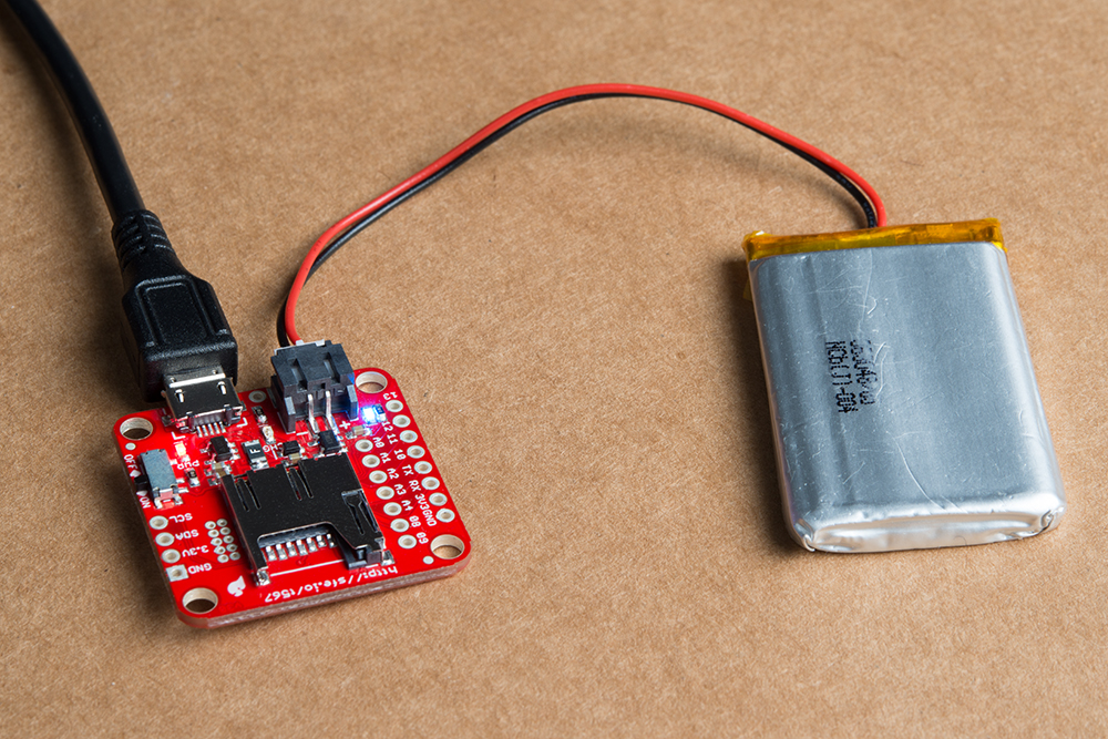
If both USB and LiPo battery are plugged into the board simultaneously, the LiPo will charge at a rate of up to 450mA. Charge status is indicated by the yellow charge LED, which will turn off when the battery is fully charged.
450mA Charge Current The maximum charge current is set by an external resistor and is not (easily) modifiable. Safe practices say not to charge your LiPo battery at greater than 1C, which means LiPo's with a capacity below about 450mAh are not recommended for use with this board.
Power from either the USB or LiPo battery sources are regulated down to 3.3V, which is used to power both the SAMD21 and MPU-9250. The regulator has a capacity for about 600mA, which means you should have plenty of current overhead left over, if you want to power other devices from the 3V3-labeled pins.
The VIN, VBAT, and GND pins can be used to supply the 9DoF Razor IMU's 3.3V regulator, instead of the USB or LiPo JST inputs. Voltage on the VIN pin should not exceed 6V, and the VBAT pin should only be connected to a single-cell LiPo battery.
Finally, the ON/OFF switch, on the bottom side of the board, controls power between both input sources and the rest of the components on the board. While in the "OFF" position, the LiPo battery will still be able to charge, but no other components should be energized.
SAMD21 and Power Supply Pin Breakouts
We've broken out as many of the SAMD21's I/O pins as the 9DoF Razor IMU's small form factor would allow us. That includes pins 10-13, analog-to-digital converter inputs A0-A4, RX, TX, and the I2C pins, SDA and SCL.
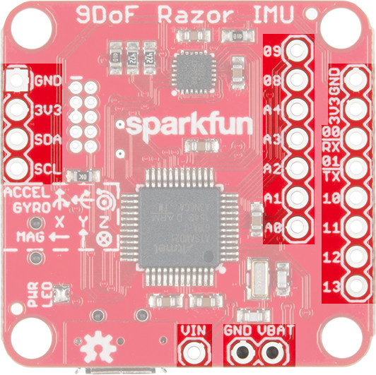
The SDA and SCL pins are on the same I2C bus as the MPU-9250, but that shouldn’t be a problem as long as any additional I2C devices don’t share the IMU’s 7-bit addresses (0x68 and 0x0C).
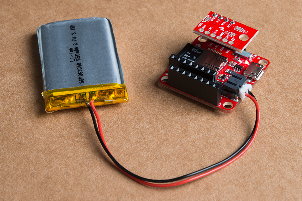
You can solder headers or wire to these pins, to expand on the board's features. For example, you can plug a BME280 breakout directly into the I2C port, and add altitude and temperature sensing to your IMU.
The SAMD21's single-wire debug (SWD) port is broken out on the top side of the board as well, in case you want to program the chip with a JTAG debugger. The pinout of this port matches the 10-pin Cortex Debug connector standard. A white "notch" indicates pin 1 of this port.
MPU-9250 Accel/Gyro/Mag Orientation
The orientation of the accelerometer, gyroscope, and magnetometer's x-, y-, and z-axes are determined by the placement of the MPU-9250. For easy reference, we've documented these vectors on the top side of the board.
Note that the magnetometer's x and y axes are flipped from those of the accelerometer and gyroscope, and the z-axis is inverted as well.
Drivers (If You Need Them)
Windows 10
The first time you plug the 9DoF Razor IMU M0 into your computer, Windows will try to search the Internet for drivers. They should automatically install for Windows 10 without any issues.
Manual Installation
If you run into issues with Windows 10, you may need to manually install drivers to enable the board's communication device class (CDC) USB profile. If your board doesn't show up as a COM port, click the button below to download the drivers.
Download the SparkFun SAMD21 Windows Drivers for Manual Installation (ZIP)
For help installing the drivers, refer to our instructions in the SAMD21 Breakout hookup guide.
Windows 7
For Windows 7, you will need to install the SAMD drivers using the SAMD Windows 7 Installer. Click on the link below to download and follow the prompts to install.
For help installing the drivers, refer to our instructions in the SAMD21 Breakout hookup guide.
Getting Started With the Example Firmware
In addition to an Arduino bootloader, we've also loaded the 9DoF Razor IMU M0 with some example firmware -- enough to at least prove that the sensor's motion tracking works, and even do a little logging to a µSD card. To start using the example firmware, simply plug the Razor IMU into a computer.
After plugging the board in, it should show up as a serial port. On Windows, that looks something like COMX and on Mac, it should look like /dev/tty.usbserial-ABCD12.
After locating your board's port, open up a serial terminal and set the baud rate to 115200 bps. The Arduino Serial Monitor works well for this purpose, or you can download one of our recommended terminal programs.
Upon opening the port, your 9DoF Razor IMU should immediately begin spouting out accelerometer, gyroscope, and magnetometer readings.
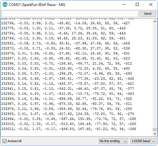
The format of this default string is:
<timeMS>, <accelX>, <accelY>, <accelZ>, <gyroX>, <gyroY>, <gyroZ>, <magX>, <magY>, <magZ> The string can be modified by sending any of the following commands:
(SPACE) -- Pause/resume serial port printingt-- Turn time readings on or offa-- Turn accelerometer readings on or offg-- Turn gyroscope readings on or offm-- Turn magnetometer readings on or offc-- Switch to/from calculated values from/to raw readingsq-- Turn quaternion readings on or off (qw, qx, qy, and qz are printed after mag readings)e-- Turn Euler angle calculations (pitch, roll, yaw) on or off (printed after quaternions)h-- Turn heading readings on or offr-- Adjust log rate in 10Hz increments between 1-100Hz (1, 10, 20, ..., 100)A-- Adjust accelerometer full-scale range. Cycles between ± 2, 4, 8, and 16g.G-- Adjust gyroscope full-scale range. Cycles between ± 250, 500, 1000, 2000 dps.s-- Enable/disable SD card logging
All settings are stored in non-volatile memory, so the next time you boot up your 9DoF Razor, it should output the same data you configured it to previously.
In addition to logging to your serial port, the firmware is also designed to log the data to a µSD card, if it's present. Load one up, and you should end up with IMU log files the next time you plug the SD card into your reader.
The 9DoF Razor IMU's firmware is available in the product's GitHub repository. To upload the firmware, you'll need the SparkFun SAMD21 board definitions and the SparkFun MPU-9250 DMP Arduino library installed on your machine. Which is exactly what we're going to document next...
Installing the 9DoF Razor Arduino Core
The 9DoF Razor IMU M0 is designed around the SAMD21 -- the same processor on the Arduino Zero -- which means adding Arduino support for the board is just a few clicks away. This section describes the steps you'll need to take to install the SAMD cores into your Arduino library (that sounds scarier than it actually is).
Update Arduino! This setup requires at least Arduino version 1.6.4 or later. We've tested it on 1.6.12, and would recommend that version of the IDE. If you're running an older version of Arduino, consider visiting arduino.cc to get the latest, greatest release.
Install Arduino SAMD Boards
First, you'll need to install a variety of tools, including low-level ARM Cortex libraries full of generic code, arm-gcc to compile your code, and bossa to upload code via the bootloader. These tools come packaged along with Arduino's SAMD board definitions for the Arduino Zero.
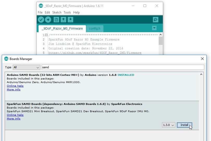
To install the Arduino SAMD board definitions, navigate to your board manager (Tools > Board > Boards Manager...), then find an entry for Arduino SAMD Boards (32-bits ARM Cortex-M0+). Select it, and install the latest version (recently updated to 1.6.8).
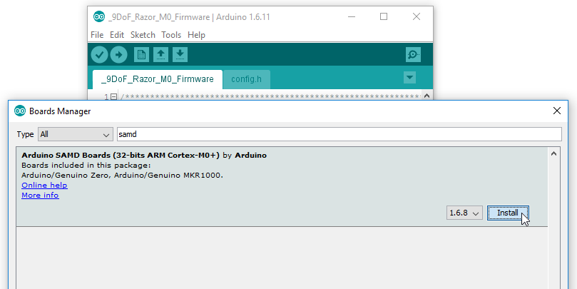
Downloading and installing the tools may take a couple minutes -- arm-gcc in particular will take the longest, it's about 250MB unpacked.
Once installed, Arduino-blue "Installed" text should appear next to the SAMD boards list entry.
Install SparkFun Board Definition
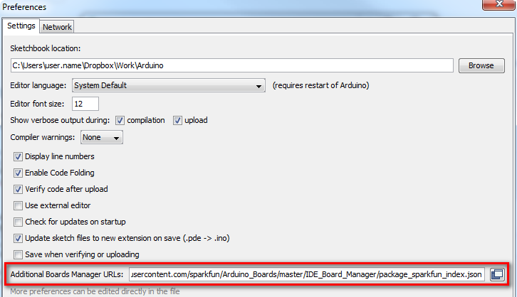
Now that your ARM tools are installed, one last bit of setup is required to add support for the SparkFun SAMD boards. First, open your Arduino preferences (File > Preferences). Then find the Additional Board Manager URLs text box, and paste the below link in:
https://raw.githubusercontent.com/sparkfun/Arduino_Boards/master/IDE_Board_Manager/package_sparkfun_index.json
Then hit "OK", and travel back to the Board Manager menu. You should be able to find a new entry for SparkFun SAMD Boards.
This installation should be much faster; you've already done the heavy lifting in the previous section.
Select the Board and Serial Port
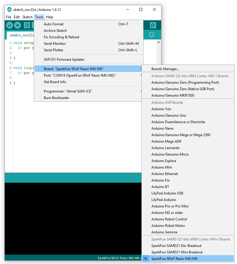
Once the board is installed, you should see a few new entries in your Tools > Board list, including SparkFun 9DoF Razor IMU M0, under the "SparkFun SAMD (32-bits ARM Cortex-M0+) Boards" menu.
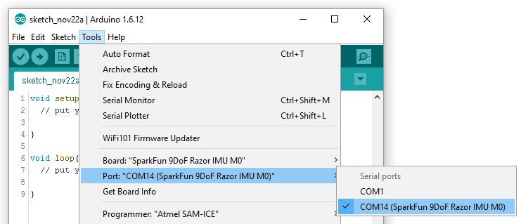
Finally, select your 9DoF Razor's port, by navigating back up to the Tools > Port menu.
In the next section, we'll load up the example firmware, so you can customize it and build upon it as you create your own motion-sensing project.
Troubleshooting
If your 9DoF Razor IMU won’t enter the bootloader, or take new code, you can force it into the bootloader by holding the SCL pin LOW on start up. Flip the IMU’s switch off, use a jumper wire to connect SCL to GND, and turn the switch back on. While in the bootloader, the blue pin 13 LED should remain illuminated.
Libraries and Example Firmware
In addition to the SAMD board definitions, the 9DoF Razor IMU M0's example firmware requires an additional library: the SparkFun MPU-9250 Digital Motion Processing (DMP) library. You can grab the MPU-9250-DMP library from GitHub, or by clicking the link below:
You'll also need the FlashStorage Arduino library installed on your machine. This library allows your SAMD21's excess flash memory to substitute for EEPROM -- giving it non-volatile memory so it can retain your serial commands.
The FlashStorage library is optional. Disable it by commenting out the ENABLE_NVRAM_STORAGE line in config.h. Without this library, settings that are changed will not be carried over on restart or power loss.
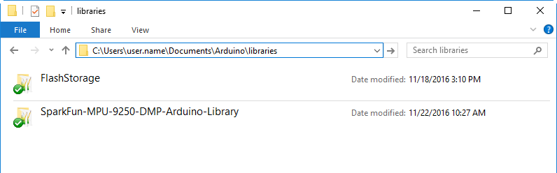
To install the libraries, unzip the ZIP files, and place the library folders into your Arduino sketchbook. For more help installing Arduino libraries, check out our Installing an Arduino Library tutorial.
After installing the libraries, open Arduino (or close and restart it if it was open).
Download and Upload the Example Firmware
The 9DoF Razor IMU M0's example firmware can be found in our 9DoF Razor GitHub repository. Or you can click the button below to download it.
The firmware includes a pair of files -- the standard .ino file with the main source, and a config.h file, which consists mostly of defines, which you can modify to quickly customize the firmware. Make sure both tabs are open in your Arduino IDE before attempting to compile and upload.
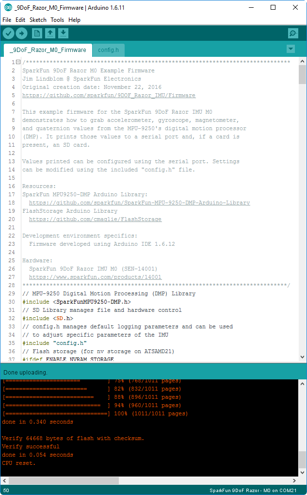
If the config.h file isn’t present in your Arduino IDE, you can create a new tab (by clicking the down-arrow in the upper-right corner of the IDE) and copy/paste it in from here.
Once you've installed the libraries, loaded the code, and have the SparkFun 9DoF Razor M0 board selected, upload it to your board. You probably won't see any new behavior on your 9DoF Razor IMU, but it'll proof that you've got everything installed correctly.
Using the MPU-9250 DMP Arduino Library
Here are some quick tips to help you get started writing your own firmware for the 9DoF Razor IMU M0 using the SparkFun MPU-9250 DMP Arduino Library.
Set Up
As with any library, to call it into your sketch you'll need to include it at the top. You'll also need to create an object of type MPU9250_DMP -- we'll make one called imu, which will be used throughout the sketch.
language:c
#include <SparkFunMPU9250-DMP.h> // Include SparkFun MPU-9250-DMP library
//#include <Wire.h> // Depending on your Arduino version, you may need to include Wire.h

MPU9250_DMP imu; // Create an instance of the MPU9250_DMP class
Then, in the setup function initialize the MPU-9250 by calling imu.begin(). You can check the return value of this function to ensure that the IMU is correctly connected and was successfully initialized.
language:c
if (imu.begin() != INV_SUCCESS)
{
    while (1)
    {
        // Failed to initialize MPU-9250, loop forever
    }
}
Note that imu.begin() – all of the error-returning functions in this library, in fact – returns a 0 on success. Check for them to return INV_SUCCESS for a more verbose error check.
Configuring the MPU-9250
Once you've initialized the MPU-9250, you can configure it to your hearts desire. You can use setSensors to enable/disable specific sensors in the IMU. Disabling the gyroscope and magnetometer, for example, can save loads of power consumption.
language:c
// Use setSensors to turn on or off MPU-9250 sensors.
// Any of the following defines can be combined:
// INV_XYZ_GYRO, INV_XYZ_ACCEL, INV_XYZ_COMPASS,
// INV_X_GYRO, INV_Y_GYRO, or INV_Z_GYRO
imu.setSensors(INV_XYZ_GYRO | INV_XYZ_ACCEL | INV_XYZ_COMPASS); // Enable all sensors
You can also set the full-scale range of both the accelerometer and gyroscope using the setAccelFSR and setGyroFSR functions. (The magnetometer only has one possible full-scale range -- ±4912 µT.)
language:c
// Use setGyroFSR() and setAccelFSR() to configure the
// gyroscope and accelerometer full scale ranges.
// Gyro options are +/- 250, 500, 1000, or 2000 dps
imu.setGyroFSR(2000); // Set gyro to 2000 dps
// Accel options are +/- 2, 4, 8, or 16 g
imu.setAccelFSR(2); // Set accel to +/-2g
The gyroscope can be set to ranges of ±250, 500, 1000, or 2000 degrees per second (dps), and the accelerometer supports ranges of ±2, 4, 8, or 16 g.
Finally, you can configure the digital low pass filter (DLPF) and sample rate of the sensors:
language:c
// setLPF() can be used to set the digital low-pass filter
// of the accelerometer and gyroscope.
// Can be any of the following: 188, 98, 42, 20, 10, 5
// (values are in Hz).
imu.setLPF(5); // Set LPF corner frequency to 5Hz

// The sample rate of the accel/gyro can be set using
// setSampleRate. Acceptable values range from 4Hz to 1kHz
imu.setSampleRate(10); // Set sample rate to 10Hz

// Likewise, the compass (magnetometer) sample rate can be
// set using the setCompassSampleRate() function.
// This value can range between: 1-100Hz
imu.setCompassSampleRate(10); // Set mag rate to 10Hz
The sample rate of the accelerometer and gyroscope can reach 1kHz, while the maximum sample rate of the magnetometer is 100Hz. The corner frequency of the low-pass filter -- which operates on the accelerometer and gyroscope only -- can be set to 5, 10, 20, 42, 98, or 188Hz.
Reading from the MPU-9250
Once your IMU is configured to fit your needs, reading from the sensor is as simple as calling imu.update() and checking the ax, ay, az, ax, ay, az, ax, ay, and mz class variables (e.g. imu.ax, imu.gy, imu.mz, etc).
language:c
// Call update() to update the imu objects sensor data. You can specify
// which sensors to update by OR'ing UPDATE_ACCEL, UPDATE_GYRO,
// UPDATE_COMPASS, and/or UPDATE_TEMPERATURE.
// (The update function defaults to accel, gyro, compass, so you don't
// have to specify these values.)
imu.update(UPDATE_ACCEL | UPDATE_GYRO | UPDATE_COMPASS);
The variables can be converted from raw, signed 16-bit values to their sensor's respective units by passing them to the calcGyro, calcAccel, and calcMag functions:
language:c
float accelX = imu.calcAccel(imu.ax); // accelX is x-axis acceleration in g's
float accelY = imu.calcAccel(imu.ay); // accelY is y-axis acceleration in g's
float accelZ = imu.calcAccel(imu.az); // accelZ is z-axis acceleration in g's

float gyroX = imu.calcGyro(imu.gx); // gyroX is x-axis rotation in dps
float gyroY = imu.calcGyro(imu.gy); // gyroY is y-axis rotation in dps
float gyroZ = imu.calcGyro(imu.gz); // gyroZ is z-axis rotation in dps

float magX = imu.calcMag(imu.mx); // magX is x-axis magnetic field in uT
float magY = imu.calcMag(imu.my); // magY is y-axis magnetic field in uT
float magZ = imu.calcMag(imu.mz); // magZ is z-axis magnetic field in uT
Using the Interrupt or Data-Ready
Instead of constantly polling the update function, you can use the MPU-9250's interrupt output to tell you when new data is ready. First, in the setup area, you should call enableInterrupt. (Don't forget to set your Arduino's interrupt pin as an input as well!)
language:c
#define INTERRUPT_PIN 4 // MPU-9250 INT pin tied to D4
...
void setup()
{
    pinMode(INTERRUPT_PIN, INPUT_PULLUP); // Set interrupt as an input w/ pull-up resistor
    ...
    // Use enableInterrupt() to configure the MPU-9250's
    // interrupt output as a "data ready" indicator.
    imu.enableInterrupt();

    // The interrupt level can either be active-high or low. Configure as active-low.
    // Options are INT_ACTIVE_LOW or INT_ACTIVE_HIGH
    imu.setIntLevel(INT_ACTIVE_LOW);

    // The interrupt can be set to latch until data is read, or as a 50us pulse.
    // Options are INT_LATCHED or INT_50US_PULSE
    imu.setIntLatched(INT_LATCHED);
}
You can set the interrupt's active level to high or low, and set it to latch until the sensor is read or to send a 50µs pulse.
Once configured, simply read the status of your Arduino's interrupt pin. If it's active, you'll know to update the IMU's sensors.
language:c
if ( digitalRead(INTERRUPT_PIN) == LOW ) // If MPU-9250 interrupt fires (active-low)
{
    imu.update() // Update all sensor's
    // ... do stuff with imu.ax, imu.ay, etc.
}
Alternatively -- if you don't want to use the interrupt pin -- you can check the return value of dataReady, to check if new data is available. This function returns a boolean -- true if new data is ready.
language:c
if ( imu.dataReady() ) // If new IMU data is available
{
    imu.update(); // Update all sensor's
    ...
}
Using the Digital Motion Processor
The MPU-9250's digital motion processor (DMP) allows you to offload tasks like quaternion calculation, step-counting, and orientation-determining off to the IMU.
Configuring the Digital Motion Processor (DMP)
To use any of those functions, you first need to initialize the DMP by calling the dmpBegin function. This should be called after imu.begin().
dmpBegin's first parameter specifies which features of the DMP you want to enable. It can be an OR'd combination of any of the following:
DMP_FEATURE_PEDOMETER-- Pedometer counts steps and the amount of time those steps were taken in.DMP_FEATURE_TAP-- Single and/or double-tap detection in any of the three planes.DMP_FEATURE_ANDROID_ORIENT-- Detects portrait, landscape, reverse portrait, and reverse landscape orientations.DMP_FEATURE_6X_LP_QUAT-- 6-axis (accelerometer and gyroscope) quaternion calculation.DMP_FEATURE_LP_QUAT-- Low-power (accelerometer only) quaternion calculation.DMP_FEATURE_GYRO_CAL-- Gyroscope calibration. After 8 seconds of no motion, the gyroscope axes are re-calibrated to 0.DMP_FEATURE_SEND_RAW_ACCEL-- Sends raw accelerometer data to the DMP's FIFO buffer.DMP_FEATURE_SEND_RAW_GYRO-- Sends raw gyroscope data to the DMP's FIFO buffer.DMP_FEATURE_SEND_CAL_GYRO-- Sends calibrated gyroscope data to the DMP's FIFO buffer.
Note that the pair of quaternion-calculating features are mutually exclusive -- only use one of those features at a time. The same goes for the calibrated and raw gyroscope data gathering features.
A second, optional parameter for dmpBegin is the update rate, which can be anywhere between 4 and 200 Hz. Here's a quick example, demonstrating how to initialize the DMP to stream accelerometer, calibrated gyroscope, and quaternion data:
language:c
void setup
{
    imu.begin(); // Initialize the MPU-9250.

    // Initialize the digital motion processor
    imu.dmpBegin(DMP_FEATURE_SEND_RAW_ACCEL | // Send accelerometer data
                 DMP_FEATURE_GYRO_CAL       | // Calibrate the gyro data
                 DMP_FEATURE_SEND_CAL_GYRO  | // Send calibrated gyro data
                 DMP_FEATURE_6X_LP_QUAT     , // Calculate quat's with accel/gyro
                 10);                         // Set update rate to 10Hz.
}
Reading from the DMP
The DMP streams its data to the MPU-9250's 512-byte first-in, first-out (FIFO) buffer, so to get data from the DMP, the FIFO must be updated. You can use the fifoAvailable function, to check how full the FIFO is. Then call dmpUpdateFifo to read from the top of the FIFO.
language:c
if ( imu.fifoAvailable() > 0 ) / Check for new data in the FIFO
{
    // Use dmpUpdateFifo to update the ax, gx, qx, etc. values
    if ( imu.dmpUpdateFifo() == INV_SUCCESS )
    {
        // The following variables will have data from the top of the FIFO:
        // imu.ax, imu.ay, imu.az, -- Accelerometer
        // imu.gx, imu.gy, imu.gz -- calibrated gyroscope
        // and imu.qw, imu.qx, imu.qy, and imu.qz -- quaternions
    }
}
Serial Output Through Hardware UART Pins
The default test code does not output serial data automatically to the hardware Tx and Rx pins. It currently outputs to the SerialUSB port (i.e. the Arduino Serial Monitor). To adjust for the Hardware Serial UART pins, adjust the config.h file on line 25 to print to the Serial1 port (i.e. pin 0 for Rx and pin 1 for Tx):
language:c
#define LOG_PORT SERIAL_PORT_USBVIRTUAL
to
language:c
#define LOG_PORT SERIAL_PORT_HARDWARE
Additionally, the default firmware is currently waiting for a "$" under our QC test procedures so you would need to comment out line 131 in the _9DoF_Razor_M0_Firmware.ino by changing:
language:c
Serial1.begin(9600);
to
language:c
//Serial1.begin(9600);
Additionally, you need to comment out line 163 in the _9DoF_Razor_M0_Firmware.ino. We recommend commenting out this section of code by adding a //'s where it says:
language:c
if ( Serial1.available() )
{
if ( Serial1.read() == '$' ) production_testing();
}
After commenting out the lines, it should look like like the following:
language:c
//if ( Serial1.available() )
//{
//  if ( Serial1.read() == '$' ) production_testing();
//}
Be sure to change the baud rate when you initialize the serial port to match the receiving serial device. The default is 115200 baud. By changing a few lines and printing the string to one of the hardware UARTs, the other serial UART that is connected can read the serial data. At a minimum, make sure to connect GND-GND, Tx-RX, and Rx-Tx. This is assuming that you are connecting the 9DoF Razor to a 3.3V device. If the other serial device can be powered at 3.3V, you can connect it to the 9DoF Razor's 3.3V pin.
If you have not used a serial UART before, try looking at this tutorial for more information about serial communication and UARTs.
Check Out the Examples!
The MPU-9250 DMP library includes a handful of examples, which demonstrate everything from getting raw sensor data from the IMU to using the digital motion processor to track steps or orientation. Check out those examples under the File > Examples > SparkFun MPU-9250 DMP Arduino Library menu as you continue working with the library.
Resources and Going Further
Our GitHub repostiory for the SparkFun 9DoF Razor IMU M0, includes all of our hardware and firmware design files. You can check out the board's schematic, Eagle PCB layout, or the example firmware over there.
For more on the 9DoF Razor IMU's MPU-9250, here are a handful of resources worth checking out:
- Datasheet (PDF)
- Register Map (PDF)
- Embedded MotionDriver 6.12 Firmware & Library -- The source and library blob for Invensense's motion processing library, which supports the MPU-9250. (Registration with Invensense required.)
- SparkFun MPU-9250 Breakout -- A small breakout for the MPU-9250, complete with an excellent hookup guide!
There are plenty of tutorials left, if you need some project inspiration. Check out some of these related tutorials:
Dungeons and Dragons Dice Gauntlet
MicroView Digital Compass
Are You Okay? Widget
Or check out this blog post for ideas: