2D Barcode Scanner Breakout Hookup Guide
 El Duderino, MAKIN-STUFF
Hardware Overview
Let's take a closer look at the DYScan DE2120 scanner module as well as the other hardware present on this breakout.
DE2120 Barcode Scanner Module
The DE2120 barcode scanner module from DYScan combines a CMOS camera with on-board image processing to identify and decode 20 different barcode symbologies in both 1D and 2D on a variety of mediums (paper, screen, etc.). The DE2120 also includes two user-configurable LEDs. One super bright white LED to help illuminate the scanning area and one red LED to project the red line like those found on laser-based scanners.
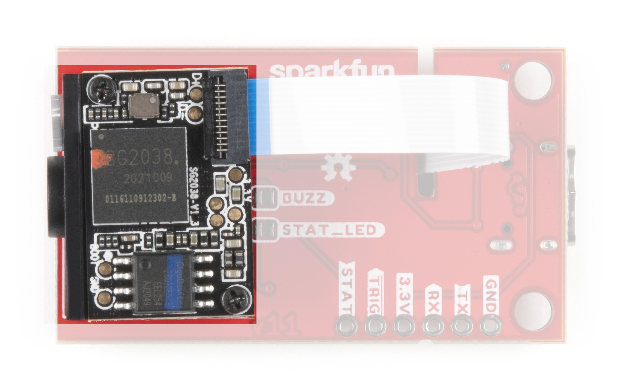
The DE2120 interfaces over USB Serial and TTL UART and can operate in several modes including USB Keyboard (default), USB COM, USB HID and TTL. Configure the communication modes and other settings by scanning barcodes or sending serial commands from the Scan Settings Manual.
When in USB Keyboard mode, the scanner behaves as a keyboard input (think your typical scanner on a Point of Sale system) and "types" the scanned barcode data followed by a carriage return. In USB-COM mode, the scanner behaves as a USB COM device and in TTL mode, the scanner operates as a TTL UART device to interface with a controller.
The module's two LEDs are also fully configurable to set behavior, brightness and simple on/off settings.
As mentioned above, the DE2120 can recognize and scan many different 1D and 2D symbologies. The list below outlines all the barcode symbologies the module recognizes:
1D Symbologies
- UPC-A
- UPC-E
- EAN-8
- EAN-13
- Code 128
- GS1-128
- Code 39
- Code 93
- Code 11
- Interleaved 2-of-5
- Matrix 2-of-5
- Industrial 2-of-5
- Codabar
- MSI
- GS1 DataBar
- Datalogic 2-of-5
2D Symbologies
- QR Code
- Data Matrix
- PDF 417
- Micro PDF 417
- Aztec Code
Pinout and USB-C Connection
The scanner module receives power either via the USB-C connector or from a regulated 3.3V source through the 3.3V pin. The scanner requires at least 190mA@3.3V to function. 5V from USB is regulated to 3.3V through an on-board 3.3V/600mA regulator.
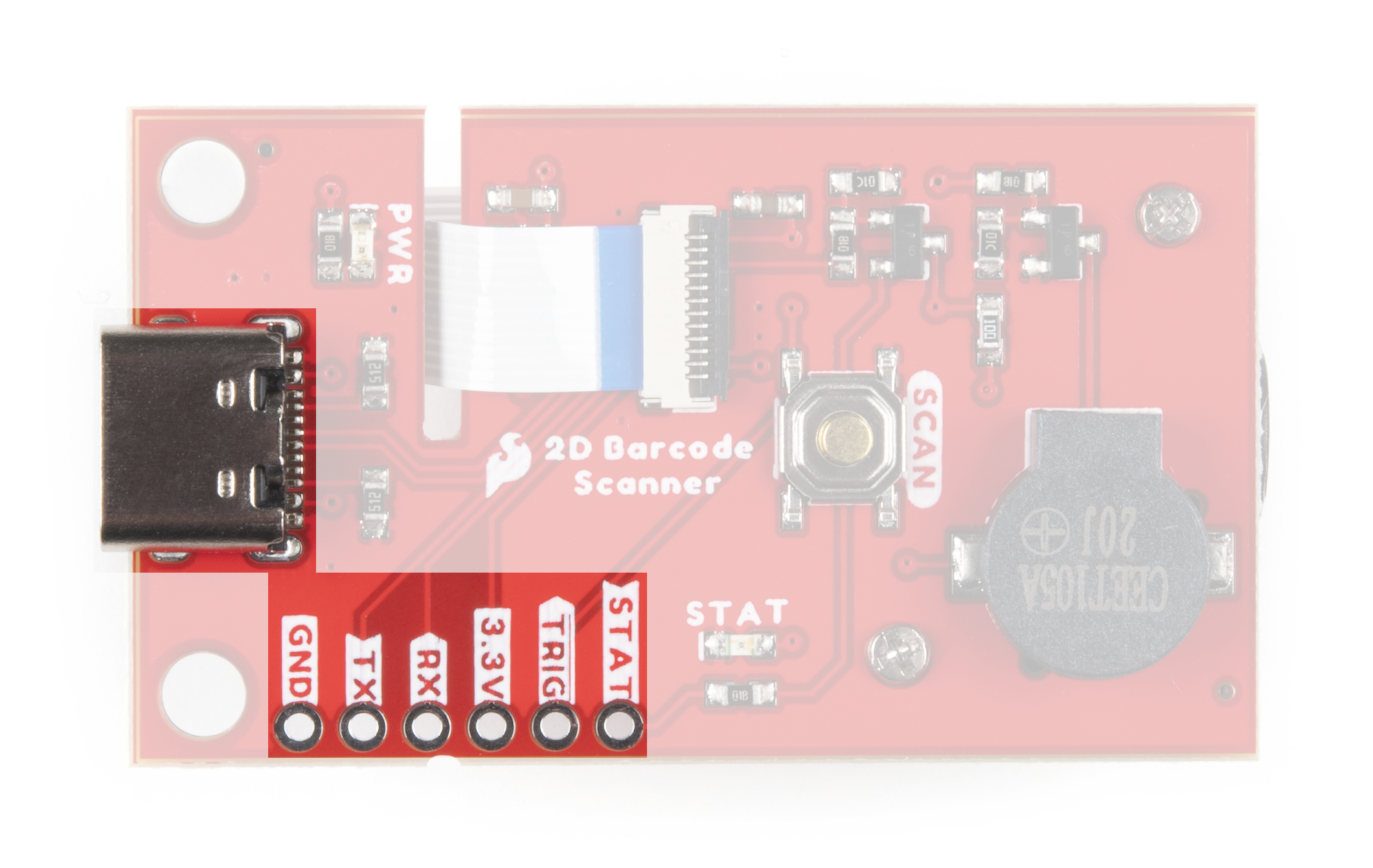
The breakout routes the power input pins (3.3V and Ground), Serial UART (RX/TX) pins as well as the Trigger Input and Status Output pins to a standard 0.1"-spaced PTH header to easily interface with them when integrating the module breakout in an installation.
Buzzer, Status LED and Trigger Button
We've routed the trigger pin to a pushbutton labeled SCAN, the status LED pin to a green LED and buzzer pin to a Piezo buzzer. Configure the Trigger and Buzzer just like everything else on the DE2120 using serial commands or barcodes from the Scan Settings Manual.
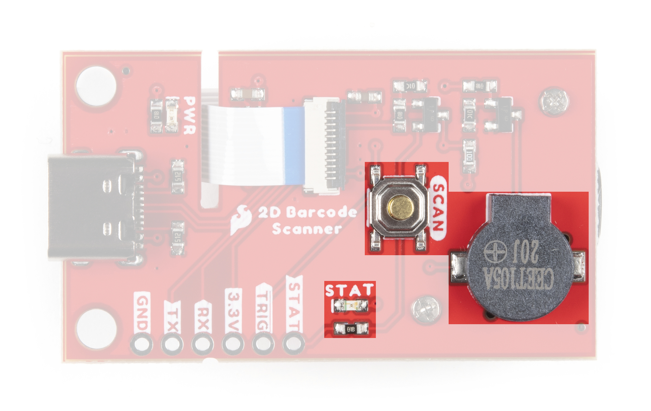
Use the Trigger Button (or pin) to initiate a scan when the DE2120 is in Trigger Mode (default). The buzzer defaults to play a tone on power-up and on a successful decode. The STAT LED illuminates on power-up and on a successful scan. The STAT LED is not configurable through software but can be disabled through the STAT LED Jumper.
Solder Jumpers
The 2D Barcode Scanner Breakout has three jumpers labeled PWR, STAT_LED and BUZZ. These three jumpers all complete their respective circuits and are CLOSED by default.
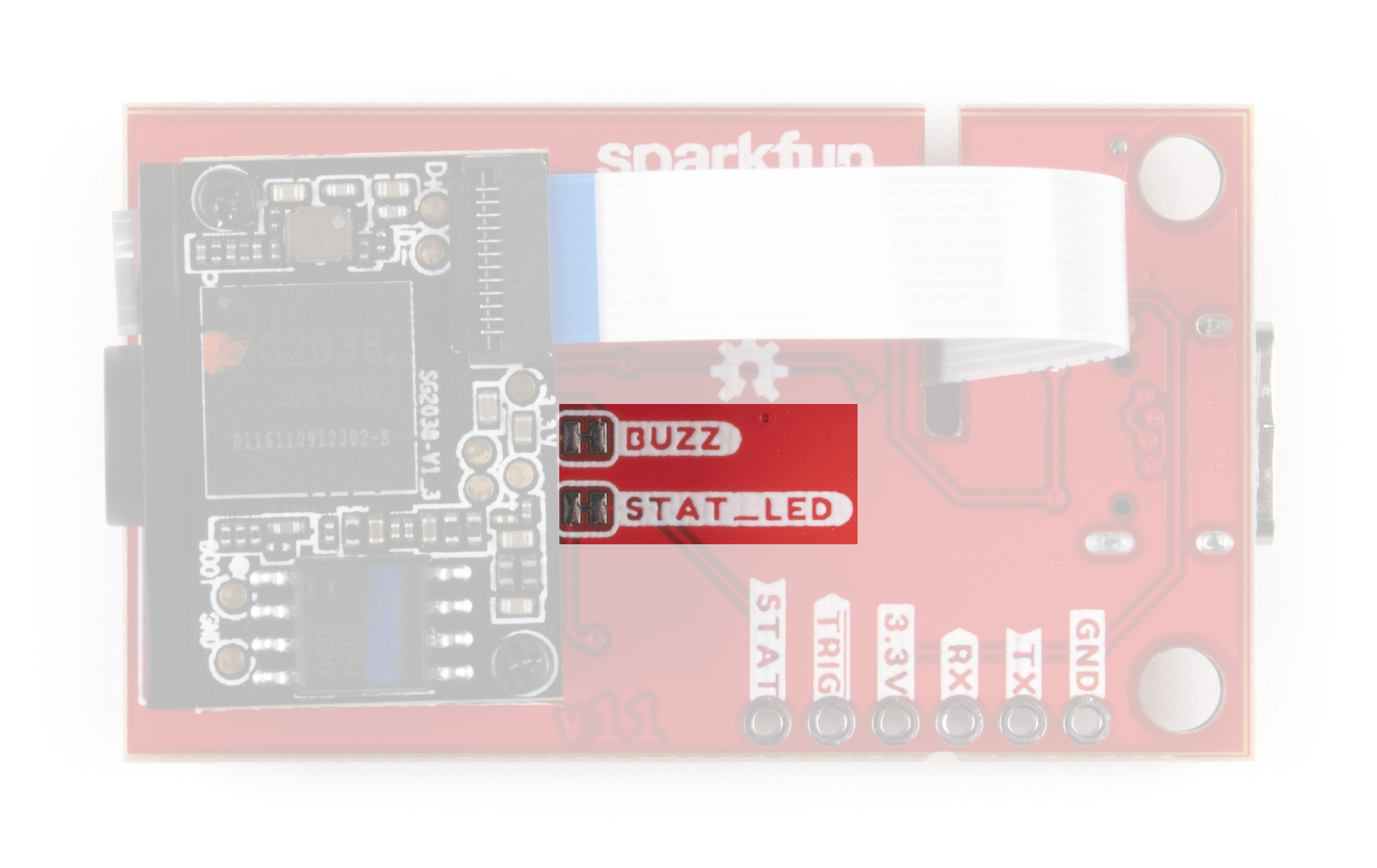
The Power LED Jumper connects the anode of the power LED to 3.3V through a 1kΩ resistor. Open the jumper by severing the trace between the two pads to disable the Power LED.
The STAT LED Jumper connects the anode of the status LED to a transistor via a 1kΩ resistor so it can be controlled by the barcode module. Open the jumper to permanently disable the Status LED on the breakout. Disabling this LED is recommended if you are using an external LED connected to the STAT PTH pin.
The Buzzer Jumper completes the buzzer driver circuit and connects the voltage input (positive) pin of the buzzer to 3.3V via a 10Ω resistor. Open the jumper to disable the on board buzzer. Similar to the STAT LED, opening this jumper is particularly useful when an external buzzer is connected to the buzzer driver PTH pin.
Board Dimensions
The 2D Barcode Scanner Breakout measures 1.75in x 1.00in (44.45mm x 25.4mm) with two mounting holes that fit a 4-40 screw.
