2D Barcode Scanner Breakout Hookup Guide
 El Duderino, MAKIN-STUFF
Hardware Assembly
Now that we're familiar with the DE2120 and other hardware present on the 2D Barcode Scanner Breakout, let's get it connected and start scanning codes.
USB Assembly
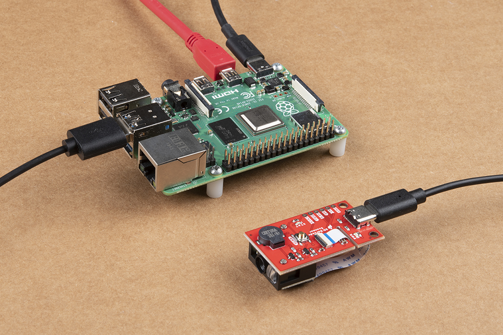
The easiest way to get started with the barcode scanner breakout is to plug it in to a computer (PC or SBC) via a USB-C cable. Simply connect the breakout to your computer using a USB-C cable and scan the USB-COM mode barcode from the Scan Setting Manual (the DE2120 defaults to USB-Keyboard mode) on page 23 or you can scan directly it below:

Once the device is in USB-COM Mode your computer should automatically search for and install the necessary drivers. After drivers are installed and the device has enumerated, select the correct port and open up a terminal window with the baud to 115200.
The DE2120 defaults to trigger mode to scan barcodes so the Trigger Button must be pressed to start a scan. Find some barcodes to scan or if you don't have any readily available, you can generate custom codes from all types of symbologies on this website to quickly test the barcode scanner.
Serial UART Assembly
Interacting with the 2D Barcode Scanner Breakout via TTL UART either through direct commands from the Scan Setting Manual or with the Arduino library requires a bit of soldering and wiring. As covered in the previous seciton, the breakout routes the required TTL UART pins to a 0.1"-spaced header for users to solder to. If you are not familiar with through-hole soldering, take a read through this tutorial:
How to Solder: Through-Hole Soldering
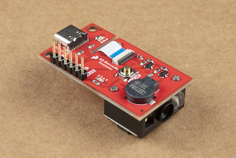
For easy prototyping in this tutorial we're going to solder a set of male headers to the breakout to easily prototype circuits using either a breadboard or jumper wires like the photo below:
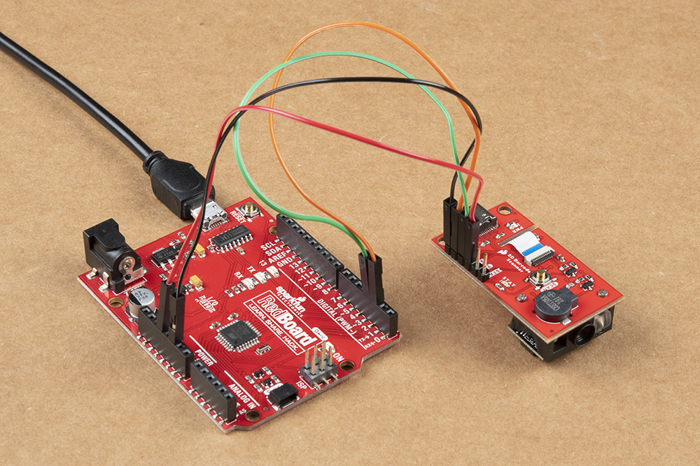
After soldering to the breakout, we make the necessary connections to the controller. In this case we'll use a SparkFun RedBoard to demonstrate the Arduino library so make the following connections or match the photo below:
2D Barcode Scanner Breakout → SparkFun RedBoard
- 3.3V → 3.3V
- GND → Ground
- TX → D2
- RX → D3
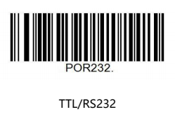
After assembling the circuit, make sure to set the 2D Barcode Scanner Breakout to operate in TTL mode by scanning the proper barcode from the Scan Setting Manual on page 24 or you can scan it below: