2D Barcode Scanner Breakout Hookup Guide
 El Duderino, MAKIN-STUFF
 Introduction

The SparkFun 2D Barcode Scanner Breakout is a nifty little breakout board featuring the DE2120 barcode scanner module from DYScan. The DE2120 reads 20 different barcode symbologies (both 1D and 2D) using a camera coupled with on-board image processing to identify and decode everything from UPC codes to QR codes. The module also features two LEDs: one for illumination and one to project the red line for "aiming" that you're used to seeing from laser-based scanners.
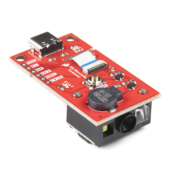
The breakout makes it easy to use the scanner module by connecting the scanner's USB serial output to a USB-C connector. The breakout also includes a standard 0.1"-spaced PTH header for the power, serial UART, trigger and status output connections. On top of that, we've added a trigger button, buzzer and status LED connected to the appropriate drive circuits to easily initialize scans and receive feedback from scanning barcodes.
Required Materials
You'll need a few things along with the 2D Barcode Scanner Breakout to follow this tutorial. You may not need everything though depending on what you have already so add anything you need from the items below to your cart.
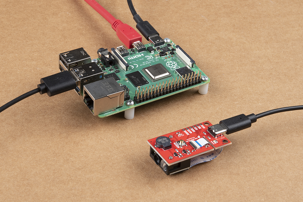
The 2D Barcode Scanner Breakout can work as a USB device connected to a computer (PC or Single-Board like the Pi) with a USB Type-C cable.


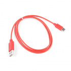
USB 2.0 Cable A to C - 3 Foot
CAB-15092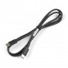
USB 2.0 C to C Cable - 1m
CAB-16395If you want to use the 2D Barcode Scanner Breakout with a Pi, the options below can get you started:
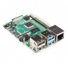
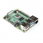
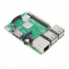
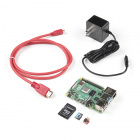
SparkFun Raspberry Pi 4 Basic Kit - 8GB
KIT-17980The breakout can also communicate with a microcontroller like an Arduino through the serial UART pins and other dedicated pins on the breakout's PTH header.


Using the breakout's PTH header requires some assembly and soldering. You may already have a few of these items but if not, the tools and hardware below will help with that assembly:


Recommended Reading
We would also recommend taking a look at the following tutorials if you aren't familiar with the concepts covered in them:
Serial Communication
Logic Levels
Serial Terminal Basics
Hardware Overview
Let's take a closer look at the DYScan DE2120 scanner module as well as the other hardware present on this breakout.
DE2120 Barcode Scanner Module
The DE2120 barcode scanner module from DYScan combines a CMOS camera with on-board image processing to identify and decode 20 different barcode symbologies in both 1D and 2D on a variety of mediums (paper, screen, etc.). The DE2120 also includes two user-configurable LEDs. One super bright white LED to help illuminate the scanning area and one red LED to project the red line like those found on laser-based scanners.
The DE2120 interfaces over USB Serial and TTL UART and can operate in several modes including USB Keyboard (default), USB COM, USB HID and TTL. Configure the communication modes and other settings by scanning barcodes or sending serial commands from the Scan Settings Manual.
When in USB Keyboard mode, the scanner behaves as a keyboard input (think your typical scanner on a Point of Sale system) and "types" the scanned barcode data followed by a carriage return. In USB-COM mode, the scanner behaves as a USB COM device and in TTL mode, the scanner operates as a TTL UART device to interface with a controller.
The module's two LEDs are also fully configurable to set behavior, brightness and simple on/off settings.
As mentioned above, the DE2120 can recognize and scan many different 1D and 2D symbologies. The list below outlines all the barcode symbologies the module recognizes:
1D Symbologies
- UPC-A
- UPC-E
- EAN-8
- EAN-13
- Code 128
- GS1-128
- Code 39
- Code 93
- Code 11
- Interleaved 2-of-5
- Matrix 2-of-5
- Industrial 2-of-5
- Codabar
- MSI
- GS1 DataBar
- Datalogic 2-of-5
2D Symbologies
- QR Code
- Data Matrix
- PDF 417
- Micro PDF 417
- Aztec Code
Pinout and USB-C Connection
The scanner module receives power either via the USB-C connector or from a regulated 3.3V source through the 3.3V pin. The scanner requires at least 190mA@3.3V to function. 5V from USB is regulated to 3.3V through an on-board 3.3V/600mA regulator.
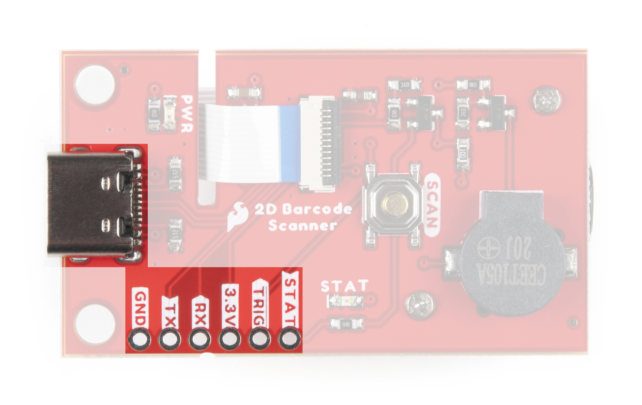
The breakout routes the power input pins (3.3V and Ground), Serial UART (RX/TX) pins as well as the Trigger Input and Status Output pins to a standard 0.1"-spaced PTH header to easily interface with them when integrating the module breakout in an installation.
Buzzer, Status LED and Trigger Button
We've routed the trigger pin to a pushbutton labeled SCAN, the status LED pin to a green LED and buzzer pin to a Piezo buzzer. Configure the Trigger and Buzzer just like everything else on the DE2120 using serial commands or barcodes from the Scan Settings Manual.
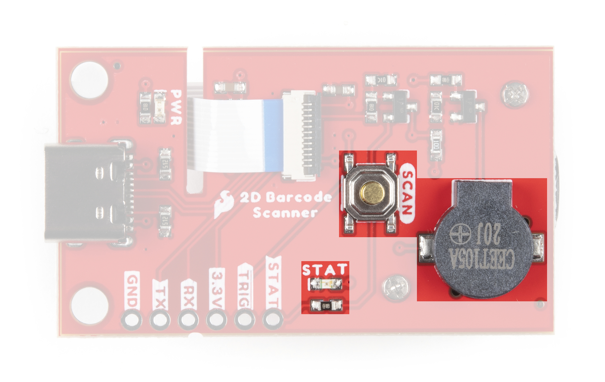
Use the Trigger Button (or pin) to initiate a scan when the DE2120 is in Trigger Mode (default). The buzzer defaults to play a tone on power-up and on a successful decode. The STAT LED illuminates on power-up and on a successful scan. The STAT LED is not configurable through software but can be disabled through the STAT LED Jumper.
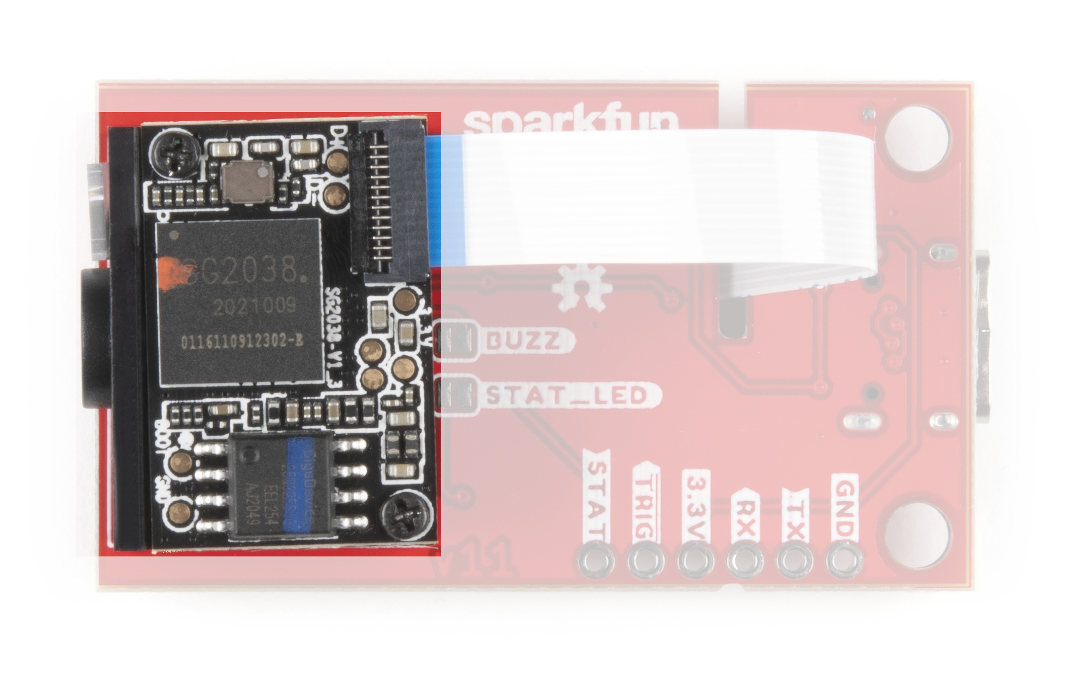
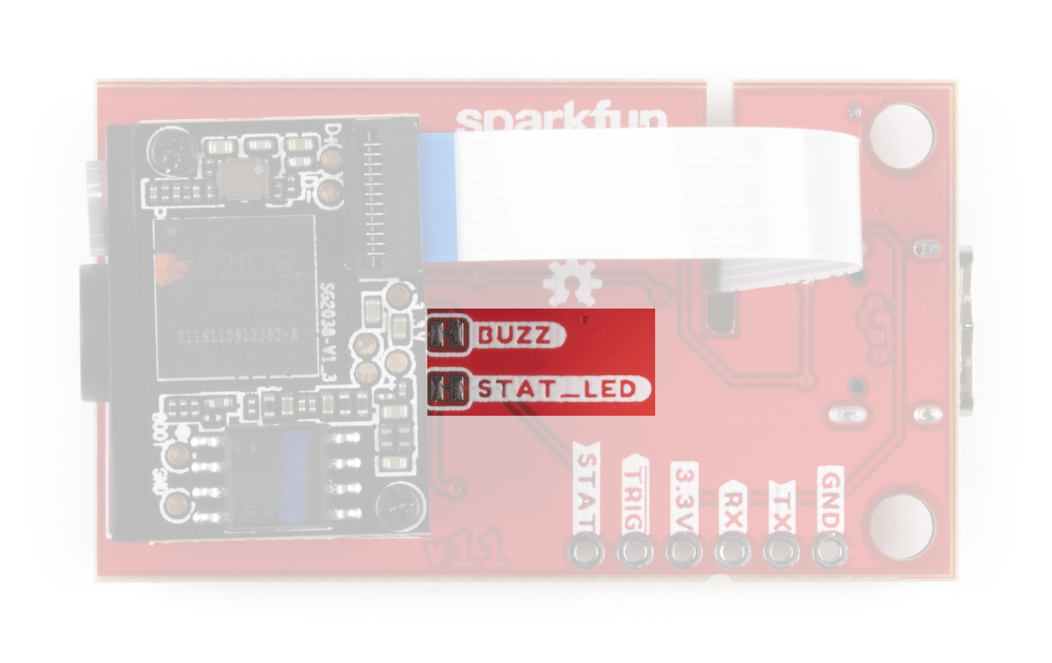
Solder Jumpers
The 2D Barcode Scanner Breakout has three jumpers labeled PWR, STAT_LED and BUZZ. These three jumpers all complete their respective circuits and are CLOSED by default.
The Power LED Jumper connects the anode of the power LED to 3.3V through a 1kΩ resistor. Open the jumper by severing the trace between the two pads to disable the Power LED.
The STAT LED Jumper connects the anode of the status LED to a transistor via a 1kΩ resistor so it can be controlled by the barcode module. Open the jumper to permanently disable the Status LED on the breakout. Disabling this LED is recommended if you are using an external LED connected to the STAT PTH pin.
The Buzzer Jumper completes the buzzer driver circuit and connects the voltage input (positive) pin of the buzzer to 3.3V via a 10Ω resistor. Open the jumper to disable the on board buzzer. Similar to the STAT LED, opening this jumper is particularly useful when an external buzzer is connected to the buzzer driver PTH pin.
Board Dimensions
The 2D Barcode Scanner Breakout measures 1.75in x 1.00in (44.45mm x 25.4mm) with two mounting holes that fit a 4-40 screw.

Hardware Assembly
Now that we're familiar with the DE2120 and other hardware present on the 2D Barcode Scanner Breakout, let's get it connected and start scanning codes.
USB Assembly
The easiest way to get started with the barcode scanner breakout is to plug it in to a computer (PC or SBC) via a USB-C cable. Simply connect the breakout to your computer using a USB-C cable and scan the USB-COM mode barcode from the Scan Setting Manual (the DE2120 defaults to USB-Keyboard mode) on page 23 or you can scan directly it below:

Once the device is in USB-COM Mode your computer should automatically search for and install the necessary drivers. After drivers are installed and the device has enumerated, select the correct port and open up a terminal window with the baud to 115200.
The DE2120 defaults to trigger mode to scan barcodes so the Trigger Button must be pressed to start a scan. Find some barcodes to scan or if you don't have any readily available, you can generate custom codes from all types of symbologies on this website to quickly test the barcode scanner.
Serial UART Assembly
Interacting with the 2D Barcode Scanner Breakout via TTL UART either through direct commands from the Scan Setting Manual or with the Arduino library requires a bit of soldering and wiring. As covered in the previous seciton, the breakout routes the required TTL UART pins to a 0.1"-spaced header for users to solder to. If you are not familiar with through-hole soldering, take a read through this tutorial:
How to Solder: Through-Hole Soldering
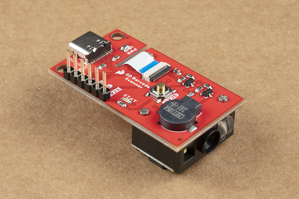
For easy prototyping in this tutorial we're going to solder a set of male headers to the breakout to easily prototype circuits using either a breadboard or jumper wires like the photo below:
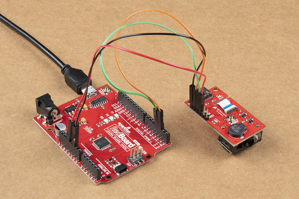
After soldering to the breakout, we make the necessary connections to the controller. In this case we'll use a SparkFun RedBoard to demonstrate the Arduino library so make the following connections or match the photo below:
2D Barcode Scanner Breakout → SparkFun RedBoard
- 3.3V → 3.3V
- GND → Ground
- TX → D2
- RX → D3
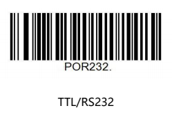
After assembling the circuit, make sure to set the 2D Barcode Scanner Breakout to operate in TTL mode by scanning the proper barcode from the Scan Setting Manual on page 24 or you can scan it below:
DE2120 Arduino Library
The SparkFun DE2120 Arduino Library helps to interface an Arduino microcontroller with the barcode scanner to configure common settings as well as poll the device for scanned codes. Note, the library does not cover all of the codes from the Scan Settings Manual; just the ones we found particularly useful.
Install the Arduino Library Manager by searching for "SparkFun DE2120 Arduino Library" and clicking the "Install" button to download and install the latest version. Users who prefer to manually install the library can get it from the GitHub Repository or you can download the repo by clicking the button below:
Library Functions
The list below goes over all the available functions in the DE2120 Library along with short descriptions of what they do. The examples use many of the functions so refer to them for demonstrations of how to use the common functions in your own code.
Class
In the global scope, construct the DE2120 object (scanner is used in the examples) without arguments:
language:c
DE2120 scanner;
Sketches should also create a character for the serial buffer and define its length for the scan data from the DE2120:
language:c
#define BUFFER_LEN 40
char scanBuffer[BUFFER_LEN];
Device Settings and Setup
The following functions control most of the settings for the DE2120 over TTL serial.
bool begin(HardwareSerial &serialPort);- Initialize communication over the hardware serial port.bool begin(SoftwareSerial &serialPort);- Initialize communication using the Software Serial library.bool isConnected();- Returns true if device's ID is what it should be.uint8_t getVersion();- Queries device for its version number.bool factoryDefault();- Sets the DE2120 to factory default settings.bool sendCommand(const char *cmd, const char *arg = "", uint32_t maxWaitInms = 3000);- Send a specific command to the DE2120. The function takes two strings as arguments, links them, adds the command prefix "^^" and the command suffix "." and then transmits the command to the module. For example, to enable Matrix 2 of 5 scanning, which is done using the command '^^M25ENA1.' you would make the call 'scanner.sendCommand("M25ENA", "1")'bool readBarcode(char *resultBuffer, uint8_t size);- Check the receive buffer for serial data. If data is present, check the result for a Carriage Return (CR). CR marks a completed scan so if found, the function overwrites the result buffer until it is full or a CR is reached in the receive buffer. Refer to Example 1 for a demonstration of this function.bool available();- Returns the number of characters in the serial buffer ready to be read.int read();- Read the data present in the serial buffer.bool changeBaudRate(uint32_t baud);- Adjust the baud rate. Default is 115200.bool changeBuzzerTone(uint8_t tone);- Adjust the buzzer's frequency between LOW, MED and HIGH.bool enableDecodeBeep();- Enable the buzzer to beep on a barcode decode.bool disableDecodeBeep();- Disable the buzzer on barcode decode.bool enableBootBeep();- Enable the buzzer to beep on startup.bool disableBootBeep();- Disable the startup buzzer beep.bool lightOn();- Turn the illuminating LED on.bool lightOff();- Turn the illuminating LED off.bool reticleOn();- Turn the red "scanner" LED on.bool reticleOff();- Turn the red "scanner" LED off.bool changeReadingArea(uint8_t percent);- Adjust the percentage of the frame area of the DE2120 to scan for barcodes. Valid options are 100%, 80%, 60%, 40% and 20%.bool enableImageFlipping();- Enable mirror image reading.bool disableImageFlipping();- Disable mirror image reading.bool USBMode(char *mode);- Enable USB communication and set the mode. Note, the DE2120 no longer communicates via TTL when this is enabled.bool enableContinuousRead(uint8_t repeatInterval = 2);- Enable continuous read mode and set the interval between scans. Default value is .bool disableContinuousRead();- Disable continuous read mode.bool enableMotionSense(uint8_t sensitivity = 50);- Enable motion sensitive read mode and set the sensitivity level. Available sensitivity values are 15, 20, 30, 50 and 100.bool disableMotionSense();- Disable motion sensitive read mode.bool enableAll1D();- Enable decoding of all 1D symbologies.bool disableAll1D();- Disable decoding of all 1D symbologies.bool enableAll2D();- Enable decoding of all 2D symbologies.bool disableAll2D();- Disable decoding of all 2D symbologies.
Polling Scan Data
These two functions are pretty straightforward and control whether or not the DE2120 is scanning for barcodes in its view area.
bool startScan();- Start scanning for barcodes.bool stopScan();- Stop scanning for barcodes.
Arduino Examples
The DE2120 Library includes three examples to demonstrate how to do simple scans, read the barcode data, configure the various settings available and sending specific commands. In this section we'll go over these examples in some detail and highlight important bits of code.
Important: Make sure to scan the barcode below to put the DE2120 into TTL mode or the barcode scanner will not communicate properly with the Arduino and the examples will freeze until the board is reset.
The 2D Barcode Scanner saves all settings during power cycles so you can configure the DE2120 however you would like (e.g. scanning mode, image flipping, LED settings, etc.) prior to assembling your Arduino circuit and using the examples.
Example 1 - Serial Scan
This basic example demonstrates how to connect the scanner to an Arduino via Software Serial and output any barcodes it sees over serial. Open the example in Arduino by navigating to "File > Examples > SparkFun DE2120 Arduino Library > Example1-SerialScan". Select the correct Board and Port from the "Tools" menu and click upload. After the upload finishes, open the serial monitor with the baud set to 115200.
Since this example uses the Software Serial library, make sure to refer to this page for pin compatibility limitations for common Arduino boards. The example assumes an ATMel328-based Arduino like the SparkFun RedBoard is used so if you prefer a different board, adjust this line if necessary:
language:c
SoftwareSerial softSerial(2, 3);
After declaring the pins to use for RX/TX in Software Serial, the code creates the scanner object as well as the scanner buffer and buffer size:
language:c
DE2120 scanner;

#define BUFFER_LEN 40
char scanBuffer[BUFFER_LEN];
The setup attempts to initialize the barcode scanner and, if successful, the main loop will start polling the buffer for any data every 200ms. If there is data in the buffer, the code prints it. With a serial monitor open, try scanning barcodes with the breakout and watch the code data print out.
Example 2 - Serial Settings
The second example shows how to adjust a selection of seven scanner settings using a "menu" in the serial monitor. Select and upload the example and open a serial monitor with the baud set to 115200. After initializing the DE2120, the code prints out the selection options for the user.
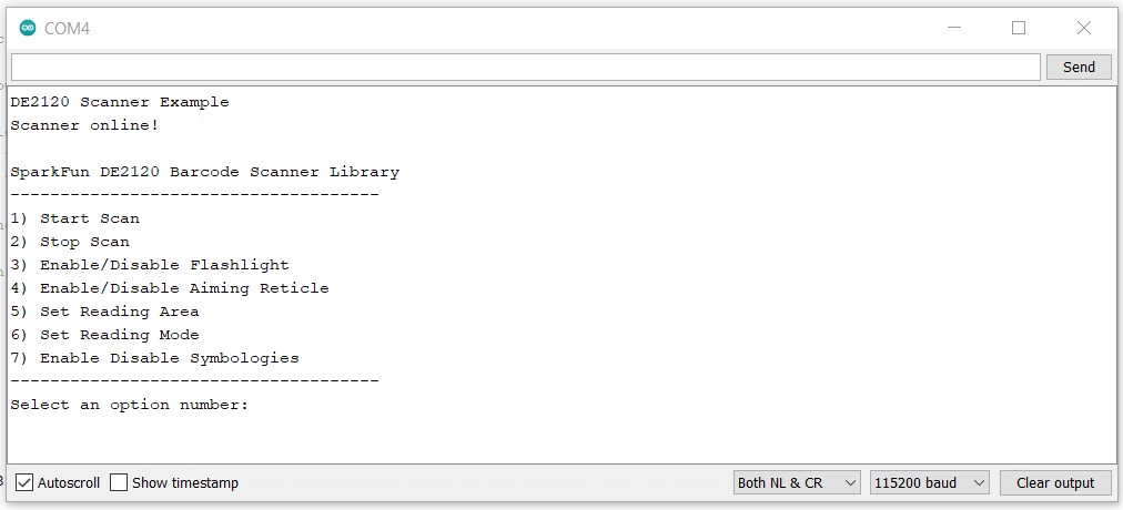
Select an option number by sending the corresponding number and hit ENTER. The code then prints out the available options for the selected setting. Enter the number corresponding to the preferred behavior and hit ENTER again to change the setting. After the setting is adjusted, the code prints if the adjustment was successful and returns to the "main menu".
Example 3 - Send Command
The third example demonstrates how to use the sendCommand(); function to send serial commands to the barcode scanner either through scanning barcodes or a serial monitor. As we mentioned in the previous section, sendCommand(); takes two strings, links them together, adds the command prefix ("^_^") and suffix (".") and sends the command to the DE2120.
Upload the example and open the serial monitor with the baud set to 115200. Once the terminal window is open, type in the command you want to use and press ENTER. Refer to the Scan Settings Manual for the Command Table (found starting on page 78). If the command is not recognized, the code prints out the code is invalid.
DE2120 Python Package
The SparkFun DE2120 Python package helps streamline sending commands and receiving barcode data from the 2D Barcode Scanner Breakout. Install the sparkfun-de2120 Python package hosted by PyPi through a command interface or if you prefer to manually download and build the libraries from the GitHub Repository, click the button below to download the package:
(Please be aware of any package dependencies. You can also check out the repository documentation page, hosted on Read the Docs.)
Installation
PyPi Installation
The DE2120 Py repository is hosted on PyPi as the sparkfun-de2120 package. On systems that support PyPi, install the package via pip3 (use pip for Python 2) using the following commands:
For all users (The user must have sudo privileges):
language:bash
sudo pip3 install sparkfun-de2120
For the current user:
language:bash
pip3 install sparkfun-de2120
Local Installation
Make sure to install the setuptools package on the system.
Direct installation at the command line (use python for Python 2):
language:bash
python3 setup.py install
Use the following command to build a package for use with pip3:
language:bash
python3 steup.py sdist
A package file is built and placed in a subdirectory called dist. Install the package file using pip3.
language:bash
cd dist
pip3 install sparkfun_de2120-<version>.tar.gz
DE2120 Python Package Operation
For a full overview of how to use this package along with all the functions included with the DE2120 Py package, take a look at the source code and package documentation hosted on ReadtheDocs.
Upgrading the Python Package
If needed, the DE2120 Python package can be upgraded using the following commands:
For all users:
language:bash
sudo pip3 install --upgrade sparkfun-de2120
For the current user:
language:bash
pip3 install --upgrade sparkfun-de2120
Python Examples
The DE2120 Python package includes three examples to demonstrate the basics of using the 2D Barcode Scanner Breakout with Python. In this section we'll cover the examples and highlight how they work.
To use the examples, open them from the DE2120 Py location or copy the code from the GitHub Repository into your preferred Python interpreter.
Reminder: The DE2120 Python Package communicates with the 2D Barcode Scanner Breakout over USB so make sure to set the DE2120 to USB-COM mode by scanning the barcode below or sending the appropriate serial command:
The 2D Barcode Scanner saves all settings during power cycles so you can configure the DE2120 however you would like (e.g. scanning mode, image flipping, LED settings, etc.) prior to using the examples.
Example 1 - Serial Scan
This basic example demonstrates how to initialize the barcode scanner and output any barcodes it reads. The example attempts to initialize the barcode scanner and, if successful, starts polling the buffer for any data every 200ms. If there is data in the buffer, the code prints it. With a terminal window open to the correct port, try scanning barcodes with the breakout and watch the decoded barcode data print out.
Example 2 - Serial Settings
This example shows how to configure various settings for the DE2120 using serial inputs sent over USB. The code creates an interactive menu for starting and stopping a scan along with the settings listed below:
- Enable/Disable Flashlight
- Enable/Disable Aiming Reticle
- Enable/Disable Decode Beep
- Enable/Disable Start Up Beep
- Change Buzzer Frequency
- Enablde/Disable Image Flipping
- Set Reading Area
- Set Reading Mode
- Enable/Disable Symbologies
Run the example and open a terminal window to the Barcode Scanner's port. To adjust a setting, type in the corresponding number and hit ENTER. A second menu for will open with the available options for the setting. Type in the number matching the preferred option and hit ENTER again. The code prints out if the setting is adjusted successfully and then returns to the main menu.
Example 3 - Send Command
The third example demonstrates how to use the send_command function to send specific command strings to the DE2120. The send_command function takes two strings, links them together, adds the command prefix ("^_^") and suffix (".") and sends the command to the DE2120.
Run the example and open a terminal window to the Barcode Scanner's port. Once the terminal window is open, type in the command you want to use and press ENTER. Refer to the Scan Settings Manual for the Command Table (found starting on page 78). If the command is not recognized, the code prints out the code is invalid.
Troubleshooting
In this section we'll cover some troubleshooting tips and tricks to help with some common snags and questions for the 2D Barcode Scanner Breakout.
USB-COM Mode Functionality Test
To make sure the Barcode Scanner Breakout is working properly, try this quick test using USB-COM mode. First, plug the breakout into your computer with a USB-C cable. Next, scan this barcode from the Scan Settings Manual to enter into USB-COM mode:
After scanning the barcode, your operating system should automatically install any drivers needed for the board. Identify the port the barcode scanner enumerated on either using Device Manager (Windows) or through the System Information menu on OS X (Mac).
With the COM port identified, open a terminal program like CoolTerm or TeraTerm, select the appropriate port, set the baud rate to 115200 and connect to the port. Once the port is open, either scan a known barcode or head over to this site to generate a unique barcode from a variety of symbologies. Press the Trigger Button to initiate the scan (if the DE2120 is in Trigger Mode) and verify the printout in the terminal window matches the barcode. If the DE2120 is not scanning any code, see the next tip.
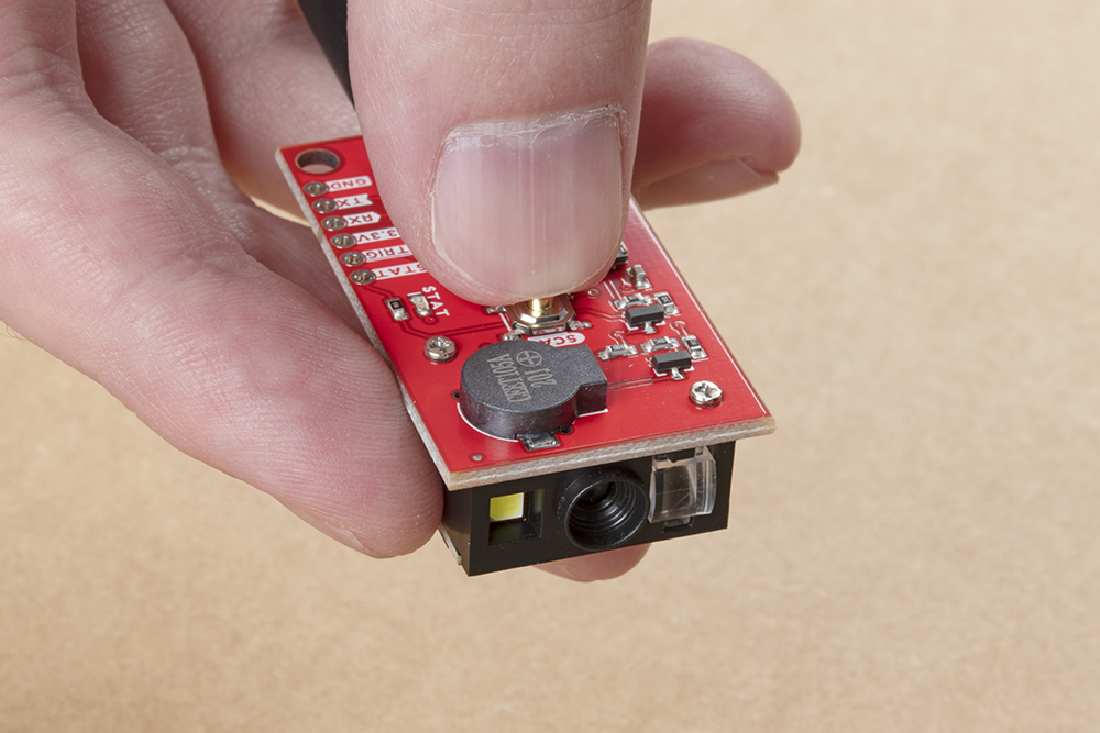
Scanner Orientation
The DE2120 has image flipping disabled by default so the scanner must be oriented properly (see image below) to scan codes. Enabling image flipping allows the DE2120 to scan codes from nearly any orientation. Turn image flipping on by scanning the corresponding barcode from the Scan Settings Manual.
Codes Matching Settings Manual
In the rare case the barcode the DE2120 scans matches a code from the Scan Settings Manual, the scanner module will interpret that as a command from the user and execute whatever that command changes on the DE2120.
General Troubleshooting and Technical Support
If you need technical assistance and more information on a product that is not working as you expected, we recommend heading on over to the SparkFun Technical Assistance page for some initial troubleshooting.
If you don't find what you need there, the SparkFun Forums are a great place to find and ask for help. If this is your first visit, you'll need to create a Forum Account to search product forums and post questions.
Resources and Going Further
That's all for this guide. For more information on the 2D Barcode Scanner Breakout check out the following resources: