WS2812 Breakout Hookup Guide
 jimblom
 Hardware Hookup
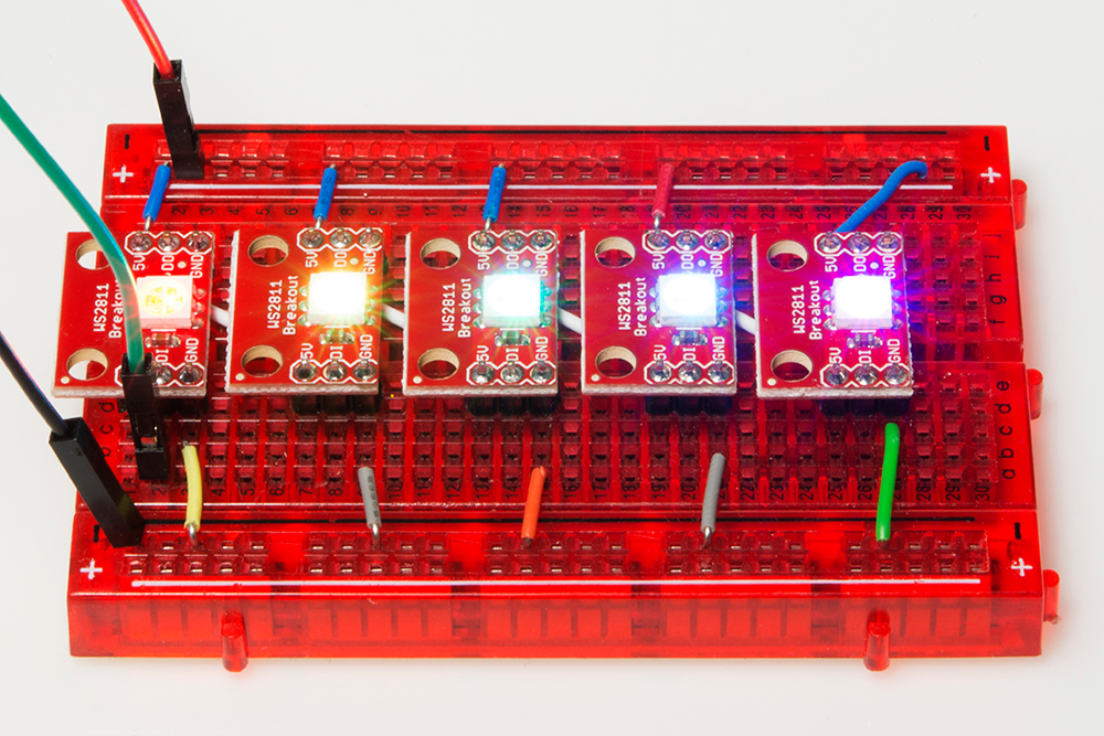
The great thing about these LEDs is they're super easy to chain together. Plus just one, single pin from your microcontroller is required to control an entire strip of LEDs. In this example, we'll link together five LEDs, but you should be safe to increase that ten-fold or even more.
Solder/Sew/Wire Something
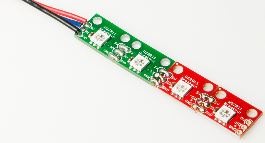
The first assembly step for each of these products is creating a reliable, electrical connection from the LED to your control board. You'll need to solder either headers or wires to your breakout boards. Or sew your LilyPad Pixel with conductive thread. Or strip and splice some wire to connect up the LED strips.
How to Solder: Through-Hole Soldering
LilyPad Basics: E-Sewing
Working with Wire
If you're going to stick the boards into a breadboard or other prototyping board, straight male headers might be the best choice.
If you're going to make a big strip of boards, you may need to opt for the stranded wire route.
Select a Power Source
The WS2812 and WS2812B requires about 5V to work. The WS2812 should operate at anywhere between about 4V to 7V while the WS2812B should operate at anywhere between about 3.3V to 5V. 5V is readily-available on most boards. The 5V header on an Arduino board, for example, is a perfect voltage supply for the LEDs.
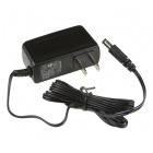
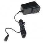
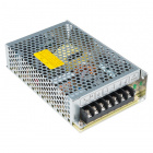
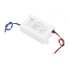
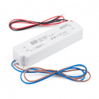
Also consider how much current your LED strip is going to pull. With every single LED on at full brightness, each breakout board can pull about 60mA (20mA per color channel). Even with just ten breakout boards strung together, you're looking at upwards of a possible 600mA. Yikes! Below are a few power supplies that can power a few addressable LEDs. You may need an additional adapter or cable to connect.
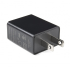
If you're stringing together a lot of these things, make sure your power supply can provide the necessary current-umph. If you end up using an external power supply, make sure you connect the power supply ground to your Arduino ground as well. Here are a few options in our catalog. Make sure to add an additional adapter to your cart as listed in the recommended products.
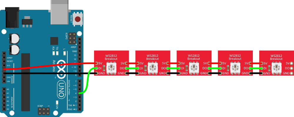
Connecting an Arduino
This hookup is fairly straightforward. You can power the breakout board(s) using the Arduino's 5V and GND pins. Then all you need is to pick a free I/O pin to send data to the LED. Let's go with pin 4. To link more breakouts together, simply connect the output pin of one to the input of the next. Make sure each breakout also gets some power delivered to it.
Protect Your WS2812's!
In addition to the hookup above, we recommend adding a capacitor and resistor as close as possible to your addressable LEDs to help you get the most out of your WS2812-based devices for long strips. Below is an example with an addressable LED strip. Read below for more information on suggested values!
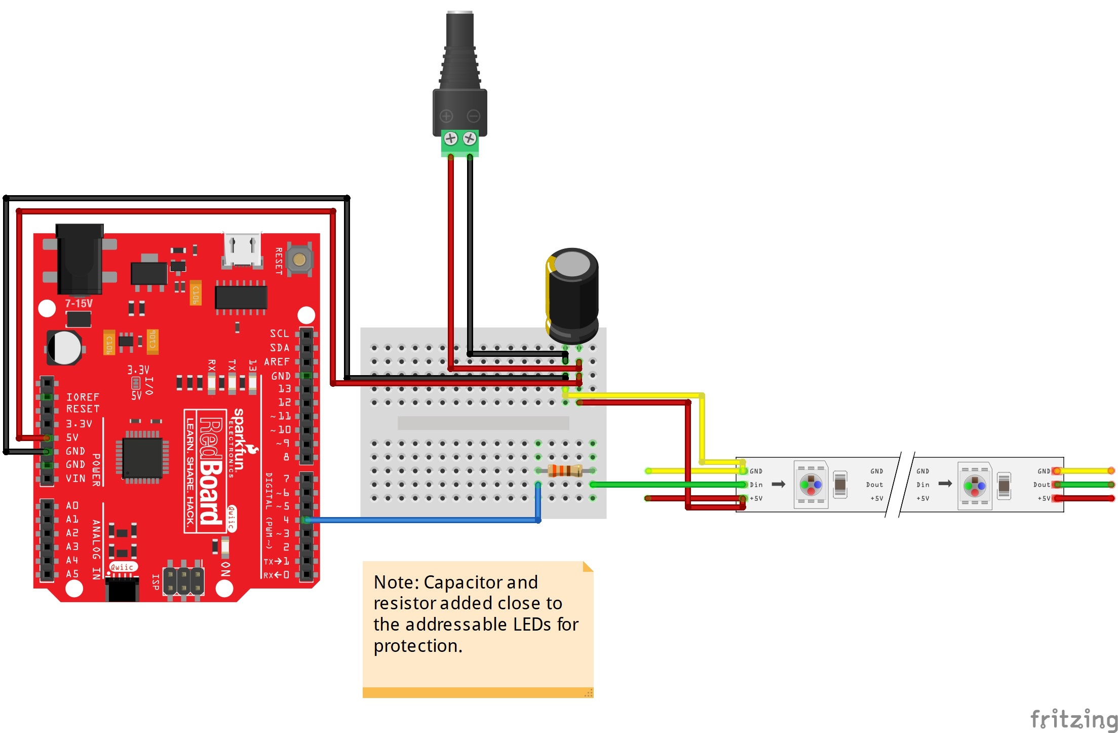
Add a Big Smoothing Capacitor
Before connecting the WS2812 to a power source, connect a big capacitor from power to ground. A cap between 100µF and 1000µF should be good.
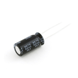
This cap will help to smooth out your power supply. The current draw of a WS2812 can vary wildly, and as current draw grows and shrinks it'll be up to your power source to compensate. The cap will act as a "power reservoir" to store energy in case the supply dips.
Try to place this cap as close to your WS2812 as possible by placing it in parallel to the Vcc and GND pins.
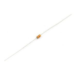
Add an In-Line Resistor On the Data Signal
Placing a small-ish resistor between your Arduino's data output and the WS2812's data input will help protect the data pin. A resistor between 220 and 470 Ω should do nicely. Try to place the resistor as close to the WS2812 as possible.
Keep Wires Short!
Wires don't conduct perfectly. They'll inevitably induce some voltage loss, especially when they're really long. Try to keep wires between your power supply, Arduino, and WS2812 as short as possible to minimize this loss.
Power Large Loads and Daisy Chained LED Strips
For more information on daisy chaining LED strips, check out this section that talks about avoiding voltage drops.
 |
| Voltage Drops Along the Daisy Chained LED Strips in Mean Well LED Switching Power Supply Hookup Guide: Power Large Loads and Daisy Chained LED Strips |