Wake-on-Shake Hookup Guide
 Toni_K,
  SFUptownMaker
Hardware Hookup
In this hardware example, we'll show you how to use the Wake-on-Shake to power up some LEDs momentarily. The LEDs could be behind a painting, on a holiday prop, or used as an indicator if something was bumped or moved.
You will need to either solder wires directly between your boards and LEDs, or solder on headers and use jumper wires between all the components. If you are unsure how to do this, please check our tutorial on soldering here.
Connect LEDs to Arduino
Take four of the LEDs, and connect them to your Arduino. For our example, we use different colored LEDs to make the hookup guide clear, but feel free to use the same color LEDs if you'd prefer.
You will want to connect the anode leg (the longer leg) of each LED to one of the digital pins. For our example, we need to use PWM capable pins.
The connections are as follows:
Anode legs of LEDs → Pro Mini
- LED1 → D3
- LED2 → D5
- LED3 → D6
- LED4 → D9
Once all the anodes are connected, you will want to connect all the cathode legs of the LEDs to ground.
Connect Wake-on-Shake to Arduino
It's now time to connect the Pro Mini to the Wake-on-Shake. There are only three pins that need to be connected between the two boards.
The connections are as follows:
Pro Mini → Wake-on-Shake
- D10 → WAKE
- RAW → VOUT
- GND → GND
D10 will drive the WAKE pin, controlling the behavior of the Wake-on-Shake. VOUT and GND need to be connected to the Arduino in order to power both the Pro-Mini and the LEDs connected to the microcontroller.
Remember that the Wake-on-Shake passes through the unregulated power from the LiPo battery, thus we attach it to the RAW pin on the Arduino to make sure the voltage from the battery gets regulated by the voltage regulator on the Pro Mini.
Power the Project
Now that everything is hooked up together, it's time to power your project. Plug the JST connector of the LiPo battery into the JST connector on the Wake-on-Shake. Your project should power on immediately, as there is no On/Off switch.
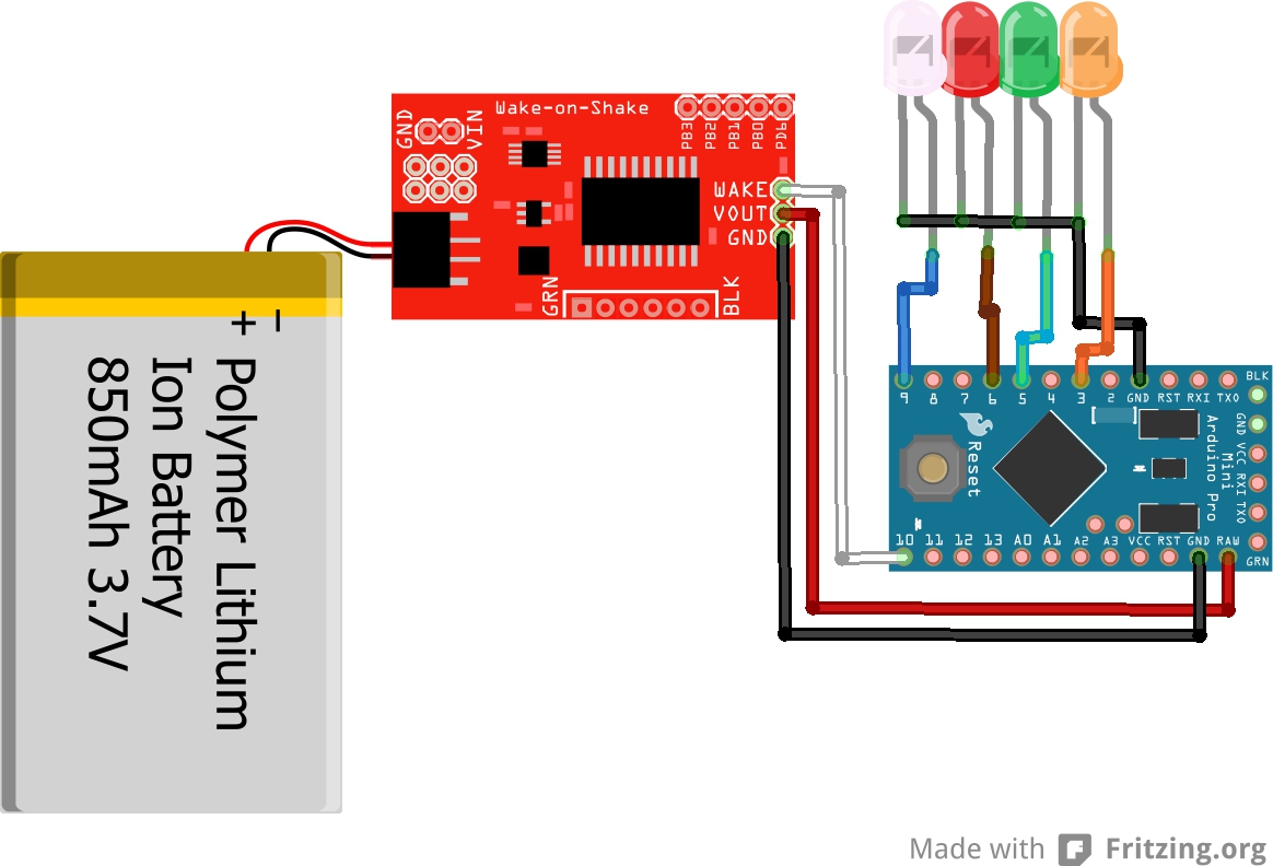
Final Circuit
Once you have everything hooked up together, your circuit should look something like the following.