Voltage Dividers
 jimblom
Applications
Voltage dividers have tons of applications, they are among the most common of circuits electrical engineers use. Here are just a few of the many places you'll find voltage dividers.
Potentiometers
A potentiometer is a variable resistor which can be used to create an adjustable voltage divider.
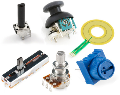
Internal to the pot is a single resistor and a wiper, which cuts the resistor in two and moves to adjust the ratio between both halves. Externally there are usually three pins: two pins connect to each end of the resistor, while the third connects to the pot's wiper.
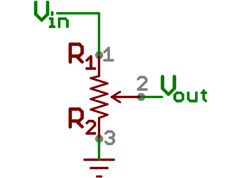
If the outside pins connect to a voltage source (one to ground, the other to Vin), the output (Vout at the middle pin will mimic a voltage divider. Turn the pot all the way in one direction, and the voltage may be zero; turned to the other side the output voltage approaches the input; a wiper in the middle position means the output voltage will be half of the input.
Potentiometers come in a variety of packages, and have many applications of their own. They may be used to create a reference voltage, adjust radio stations, measure position on a joystick, or in tons of other applications which require a variable input voltage.
Reading Resistive Sensors
Many sensors in the real world are simple resistive devices. A photocell is a variable resistor, which produces a resistance proportional to the amount of light it senses. Other devices like flex sensors, force-sensitive resistors, and thermistors, are also variable resistors.
It turns out voltage is really easy for microcontrollers (those with analog-to-digital converters - ADC’s - at least) to measure. Resistance? Not so much. But, by adding another resistor to the resistive sensors, we can create a voltage divider. Once the output of the voltage divider is known, we can go back and calculate the resistance of the sensor.
For example, the photocell's resistance varies between 1kΩ in the light and about 10kΩ in the dark. If we combine that with a static resistance somewhere in the middle - say 5.6kΩ, we can get a wide range out of the voltage divider they create.

| Light Level | R2 (Sensor) | R1 (Fixed) | Ratio R2/(R1+R2) | Vout |
| Light | 1kΩ | 5.6kΩ | 0.15 | 0.76 V |
| Dim | 7kΩ | 5.6kΩ | 0.56 | 2.78 V |
| Dark | 10kΩ | 5.6kΩ | 0.67 | 3.21 V |
A swing of about 2.45V from light to dark. Plenty of resolution for most ADCs!
Level Shifting
More complicated sensors may transmit their readings using heavier serial interfaces, like a UART, SPI, or I2C. Many of those sensors operate at a relatively low voltage, in order to conserve power. Unfortunately, it's not uncommon that those low-voltage sensors are ultimately interfacing with a microcontroller operating at a higher system voltage. This leads to a problem of level shifting, which has a number of solutions including voltage dividing.
For example, an ADXL345 accelerometer allows for a maximum input voltage of 3.3V, so if you try to interface it with an Arduino (assume operating at 5V), something will need to be done to step down that 5V signal to 3.3V. Voltage divider! All that's needed is a couple resistors whose ratio will divide a 5V signal to about 3.3V. Resistors in the 1kΩ-10kΩ range are usually best for such an application; let's
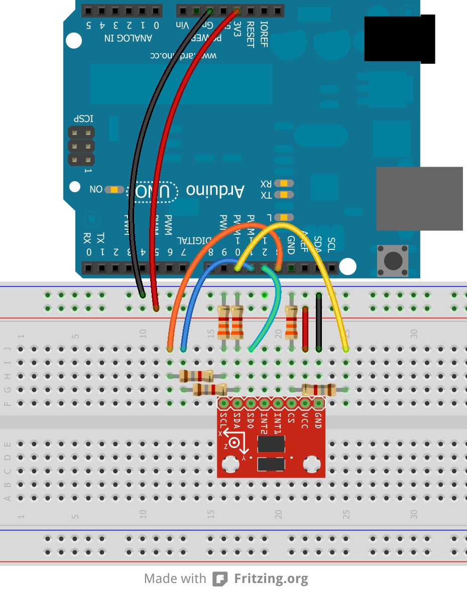
Keep in mind, this solution only works in one direction. A voltage divider alone will never be able to step a lower voltage up to a higher one.
Application Dont's
As tempting as it may be to use a voltage divider to step down, say, a 12V power supply to 5V, voltage dividers should not be used to supply power to a load.
Any current that the load requires is also going to have to run through R1. The current and voltage across R1 produce power, which is dissipated in the form of heat. If that power exceeds the rating of the resistor (usually between ⅛W and 1W), the heat begins to become a major problem, potentially melting the poor resistor.
That doesn't even mention how inefficient a voltage-divider-power-supply would be. Basically, don't use a voltage divider as a voltage supply for anything that requires even a modest amount of power. If you need to drop down a voltage to use it as a power supply, look into voltage regulators or switching supplies.