Voltage Dividers
Ideal Voltage Divider
There are two important parts to the voltage divider: the circuit and the equation.
The Circuit
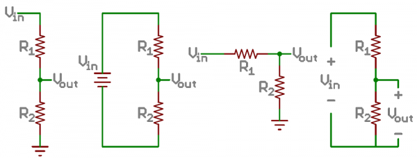
A voltage divider involves applying a voltage source across a series of two resistors. You may see it drawn a few different ways, but they should always essentially be the same circuit.
We'll call the resistor closest to the input voltage (Vin) R1, and the resistor closest to ground R2. The voltage drop across R2 is called Vout, that's the divided voltage our circuit exists to make.
That's all there is to the circuit! Vout is our divided voltage. That's what'll end up being a fraction of the input voltage.
The Equation
The voltage divider equation assumes that you know three values of the above circuit: the input voltage (Vin), and both resistor values (R1 and R2). Given those values, we can use this equation to find the output voltage (Vout):
This equation states that the output voltage is directly proportional to the input voltage and the ratio of R1 and R2. If you'd like to find out where this comes from, check out this section where the equation is derived. But for now, just write it down and remember it!
Calculator
Have some fun experimenting with inputs and outputs to the voltage divider equation! Below, you can plug in numbers for Vin and both resistors and see what kind of output voltage they produce.
Or, if you adjust Vout, you'll see what resistance value at R2 is required (given a Vin and R1).
Simplifications
There are a few generalizations that are good to keep in mind when using voltage dividers. These are simplifications that make evaluating a voltage dividing circuit just a little easier.
First, if R2 and R1 are equal then the output voltage is half that of the input. This is true regardless of the resistors' values.
If R2 is much larger (at least an order of magnitude) than R1, then the output voltage will be very close to the input. There will be very little voltage across R1.
Conversely, if R2 is much smaller than R1, the output voltage will be tiny compared to the input. Most of the input voltage will be across R1


