Triple Axis Accelerometer Breakout - KX13x (Qwiic) Hookup Guide
Hardware Overview
In this section we'll cover the unique aspects of the KX134 and KX132 accelerometers along with other components found on the Triple Axis Accelerometer Breakout - KX13x (Qwiic).
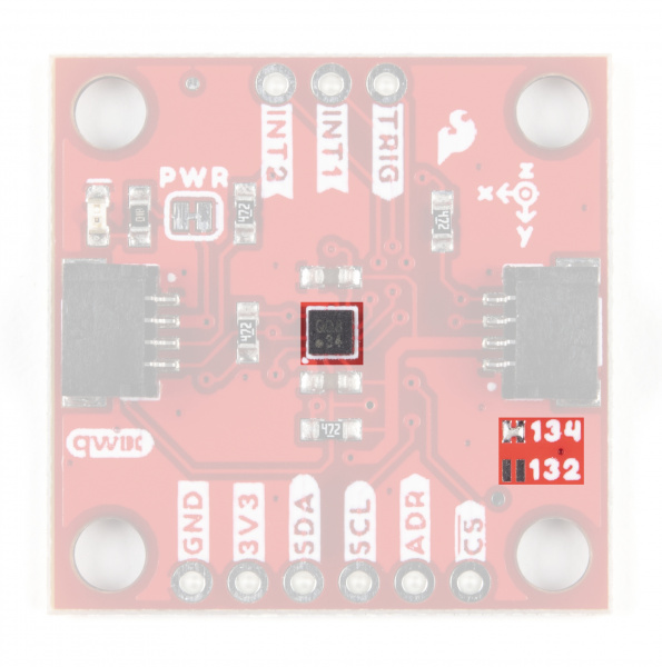
KX132 & KX134 3-Axis Accelerometers
First up let's examine the two accelerometers on the boards, highlight their specifications and how they differ. The KX134-1211 and KX132-1211 offer the following features:
- Four User-Selectable Measurement Ranges
- KX134: ±8 / 16 / 32 / 64g
- KX132: ±2 / 4 / 8 / 16g
- User-configurable 3-stage Advanced Data Path (ADP) with low-pass filter, low-pass/high-pass filter and RMS calculation engine
- User-selectable Low Power or High-Performance Modes
- Configurable Output Data Rate (ODR) up to 25,600Hz
- High resolution Wake-Up / Back-to-Sleep functions with configurable thresholds (as low as 15.6mg on the KX134 & 39mg on the KX132)
- Free fall detection
- Directional-Tap™/Double-Tap™
- Device Orientation algorithms
- Embedded 512-byte FIFO buffer (continues to record while being read)
- Digital I2C up to 3.4MHz and Digital SPI up to 10MHz
The KX13x also includes an integrated voltage regulator to maintain consistent performance across its entire supply voltage range (1.7 to 3.6V). The table below outlines some of the electrical and functional characteristics of the KX134-1211 and KX132-1211 from the sensors' datasheets. All values in the table apply to both accelerometers unless specifically noted in the table or notes below it. Refer to the accelerometers' datasheets for a full overview: KX132-1211 & KX134-1211.
| Parameter | Units | Min | Typical | Max | |
|---|---|---|---|---|---|
| Supply Voltage (VDD) | V | 1.7 | 2.5 (3.3 for use with Qwiic) | 3.6 | |
| Current Consumption (Accelerometer Only) | High Performance w/Wake-up Detection (ODR=800Hz) | µA | 148 | ||
| Low Power w/Wake-up Detection (ODR=0.781Hz, 2 samples averaged) | 0.53 | ||||
| Standby | 0.50 | ||||
| Operating Temperature Range | °C | -40 | - | 105 | |
| Output Data Rate | Hz | 0.781 | 50 | 25600 | |
| Sensitivity (16 bit) | ±2g[1] | counts/g | 14501 | 16384 | 17367 |
| ±4g[1] | 7700 | 8192 | 8684 | ±8g | 3768 | 4096 | 4424 |
| ±16g | 1884 | 2048 | 2212 | ||
| ±32g[2] | 942 | 1024 | 1106 | ||
| ±64g[2] | 471 | 512 | 553 | ||
| Noise[3] | RMS | mg | KX134: 1.9 | ||
| KX132: 0.7 | |||||
| Density | µg/√Hz | KX134: 300 | |||
| KX132: 150 | |||||
| I2C Address | 0x1E (0x1F alternate) | ||||
2. Reminder: ±32/64g ranges are only availabe on the KX134.
3. Acceleration data noise varies depending on ODR, power mode & Average Filter Control settings. Noise measuring settings: High-Performance Mode (RES=1), ODR=50Hz, IIR Filter Enabled and IIR filter corner frequency set to ODR/2. Refer to Table 1 in the sensors' Datasheets as well as the Technical Reference Manuals for more information.
Pinout
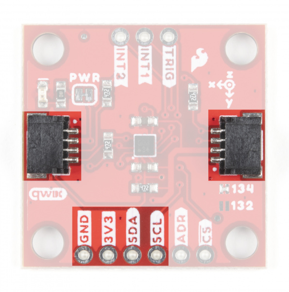
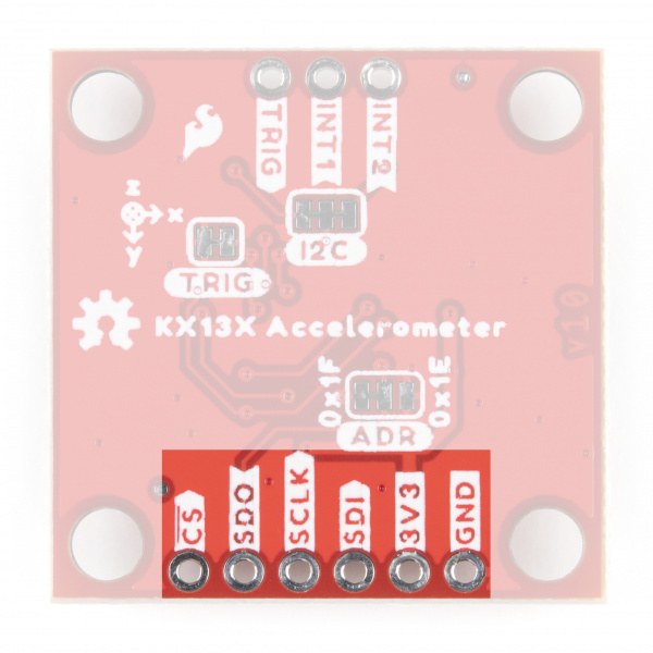
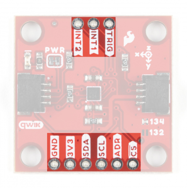
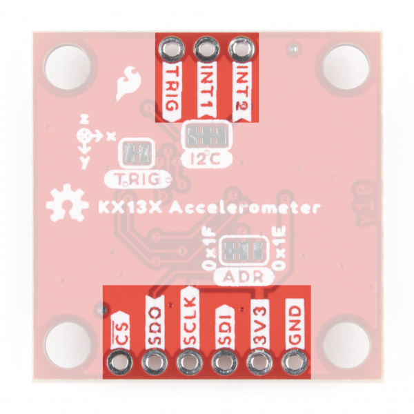
The KX13x Breakouts' I2C and SPI interface share the same pins so users must select the interface mode by altering the state of the ADR/SDO pin. The ADR jumper sets the state of the ADR/SDO pin (more on that in the Solder Jumpers section). Both breakouts operate in I2C mode by default. We've labeled these shared pins so I2C labels are visible from the front and SPI labels are visible when viewed from the back.
 |
 |
Qwiic and I2C Interface
As you would expect on a Qwiic breakout, the boards break out the KX134's I2C pins to a pair of Qwiic connectors to easily integrate the board into a Qwiic system. The I2C pins are also routed to a standard 0.1" spaced header for PTH soldering.
SPI Interface
Communicating via SPI on the Qwiic KX13x is ideal for taking advantage of the maximum Output Data Rate as the Digital SPI interface on the KX13x-1211 can operate at speeds up to 10MHz.
The Qwiic KX13x breaks out the SPI interface to the same standard 0.1" spaced header as the I2C pins. As mentioned above, the board ships with the I2C interface enabled by default so to switch to the SPI interface users need to open the ADR jumper by severing the trace in between the "Center" and "Left" pads and connect the SDO/ADR pin to SDI/CIPO on your microcontroller.
Interrupt and Trigger Pins
The KX13x has two physical interrupt pins as well as a trigger pin for FIFO buffer control. Both of the physical interrupts operate as push-pull, enter a high-impedence (high-Z) state during the Power-On-Reset (POR) procedure and are driven LOW after POR. Connect these pins to external interrupt-capable pins on your microcontroller to use the interrupt functionalities. Refer to the Interrupt and Buffer examples in the Qwiic KX13x Arduino and Python libraries for a demonstration of using the interrupt pins.
The Trigger pin controls the FIFO buffer. By default, the Qwiic KX13x ties this pin to ground through the TRIG jumper. Users who wish to use the Trigger pin must open that jumper before tying it to a pin on their microcontroller. Refer to the Datasheets (KX132 & KX134) and either Technical Reference Manuals (KX132 or KX134) for more information on using this pin to control the FIFO buffer.
Solder Jumpers
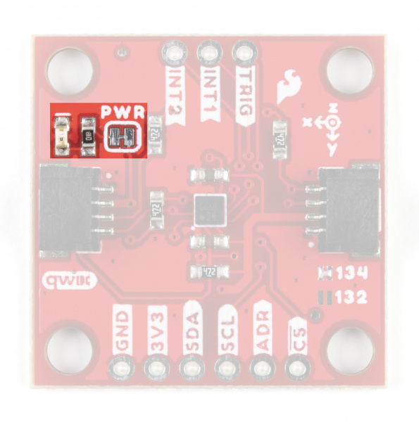
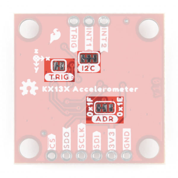
The Qwiic KX13x has four jumpers labeled ADR, I2C, TRIG and PWR. In this section we'll cover each jumper's purpose, their default states and how to configure them to alter the functionality of the KX13x Breakouts.
 |
 |
Address (ADR) Jumper
This 3-way jumper selects the I2C address of the KX13x and also selects the communication interface for the chip by pulling the ADR/SDO pin to either 3.3V, 0V/Ground or No Connect. By default, the ADR/SDO is pulled to 3.3V via a 4.7kΩ resistor to set the KX134 to operate in I2C mode with the I2C address as 0x1E.
To change the I2C address to 0x1F, sever the trace between the "Center" and "Left" pads and then connect the "Center" and "Right" pads together to pull the ADR/SDO pin to 0V/Ground.
Finally, to set the Qwiic KX13x to SPI mode, sever the trace between the "Center" and "Left" pads of the ADR jumper (default setting) to leave the ADR/SDO pin Floating/No Connect. After adjusting the jumper, connect the SDO pin to your controller's SDI/COPI pin.
I2C Jumper
The I2C jumper on the Qwiic KX13x pulls the SDA and SCL lines to 3.3V via a pair of 4.7kΩ resistors. The default state of this jumper is CLOSED. Open the jumper by severing the traces between the three pads to disable the pullups on these lines.
If you have more than one device on a single I2C bus, best practices recommend to only maintain a single pair of pullup resistors to avoid creating too strong of a parallel resistance. A strong parallel resistance can lead to communication issues on the bus. Take note that if you are using a single set of pull-up resistors on your I2C bus, make sure all devices operate at the same logic level or are properly shifted to avoid damage to the device(s).
Trigger (TRIG) Jumper
The Trigger jumper ties the TRIG pin on the KX13x-1211 to 0V/Ground. The default state of this jumper is CLOSED. To use the Trigger pin for FIFO control, open the jumper and connect the TRIG PTH pin to a digital I/O pin on your microcontroller. Refer to section 2.5 in the Technical Reference Manuals (KX132 or KX134) for more information on using Trigger Mode.
Power LED (PWR) Jumper
The Power LED jumper (labeled PWR on the board) completes the power LED circuit on the board by tying the anode of the LED to 3.3V via a 1kΩ resistor. The jumper is CLOSED by default. Disable the power LED by severing the trace between the two pads. Disabling the LED helps reduce the total current draw of the board and is particularly helpful for low-power or battery-powered applications.
Board Dimensions
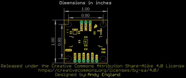
The Triple Axis Accelerometer Breakout - KX13x (Qwiic) matches the standard 1x1" (25.4mm x 25.4mm) dimensions for Qwiic breakouts and has four mounting holes that fit a 4-40 screw.
