Transparent Graphical OLED Breakout Hookup Guide
 Liquid Soulder, Ell C
Hardware Hookup
Now that you know what's available on your breakout board we can check out the options for connecting it to the brains of your project. There are two options to use - either I2C or SPI - and they each have their own advantages and drawbacks. Read on to choose the best option for your setup.
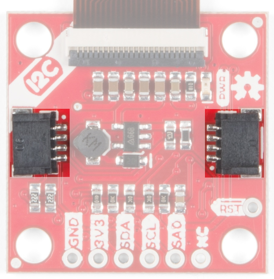
I2C (Qwiic)
The easiest way to start using the Transparent Graphical OLED is to use a Qwiic Cable along with a Qwiic compatible microcontroller (such as the ESP32 Thing Plus). You can also use the Qwiic Breadboard Cable to attach any I2C capable microcontroller, or take the scenic route and solder in all the I2C wires to the plated-through connections on the board.
 |
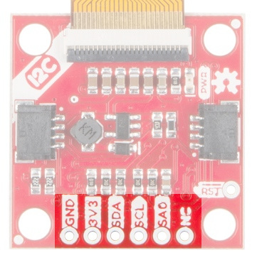 |
So why use I2C? It's easy to connect with the Qwiic system, and you can put up to two of the Transparent Graphical Breakouts on the same bus without using any more microcontroller pins. That simplicity comes at a cost to performance though. The maximum clock speed of the I2C bus is 400 kHz, and there is additional overhead in data transmission to indicate which bytes are data and which are commands. This means that the I2C connection is best for showing static images.
| Breakout Pin | Microcontroller Pin Requirements |
|---|---|
| GND | Ground pin. Connect these so the two devices agree on voltages |
| 3V3 | 3.3V supply pin, capable of up to 400 mA output |
| SDA | SDA - the bi-directional data line of your chosen I2C port |
| SCL | SCL - the clock line of your chosen I2C port |
| SA0 | Optional : change the I2C address of the breakout. Make sure to cut JP2 |
| RST | Optional : reset the breakout to a known state by pulsing this low |
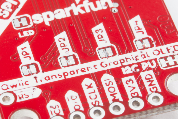
SPI
SPI solves the I2C speed problems. With SPI there is a control signal that indicates data or command and the maximum clock speed is 10 MHz -- giving SPI 50x more speed! However, it doesn't have the same conveniences of the polarized Qwiic connector and low pin usage. You'll need to solder to the pins.
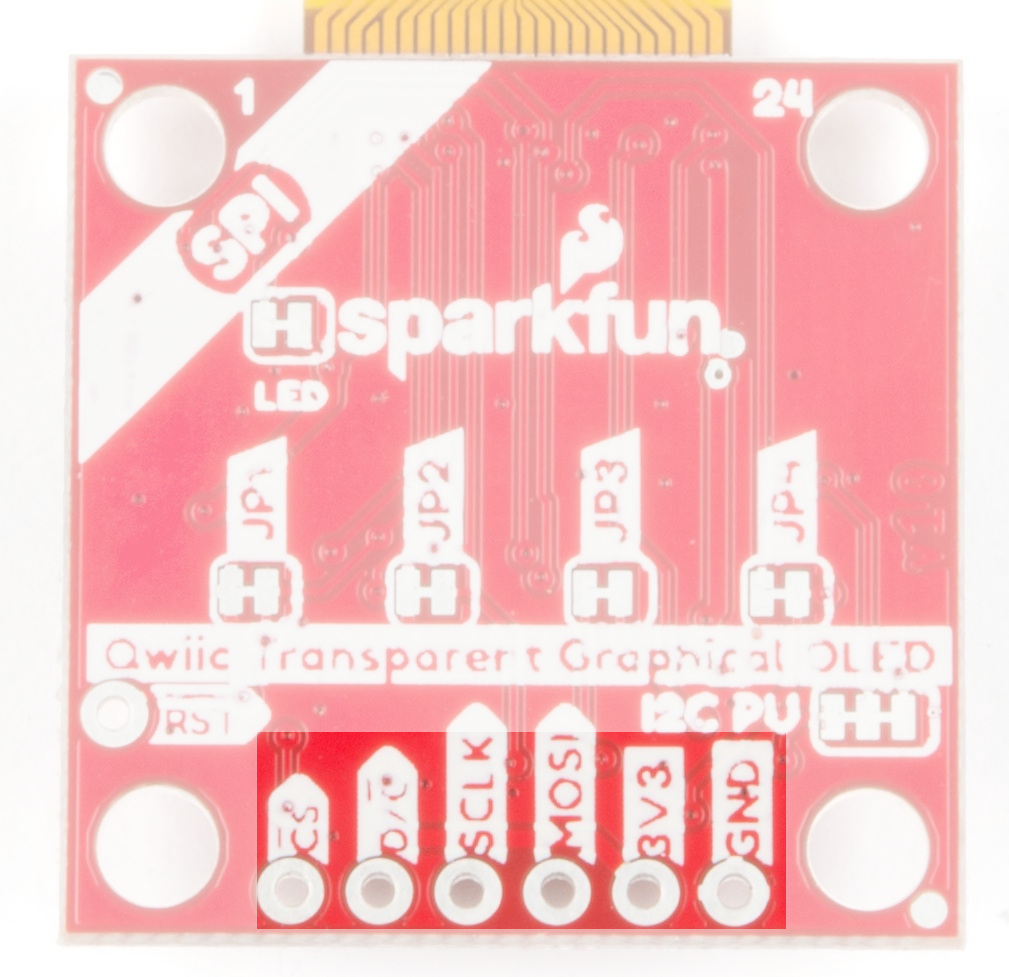
You can use SPI to connect as many breakouts as you want. For N displays you will need to use at least N + 3 data pins. That's because the MOSI, SCLK, and D/C pins can be shared between displays but each breakout needs its own dedicated Chip Select (CS) pin.
| Breakout Pin | Microcontroller Pin Requirements |
|---|---|
| CS | A GPIO pin, set low when talking to the breakout |
| D/C | A GPIO pin, indicates if bytes are data or commands |
| SCLK | The clock output of your chosen SPI port |
| MOSI | The data output of your chosen SPI port |
| 3V3 | 3.3V supply pin, capable of up to 400 mA output |
| GND | Ground pin. Connect these so the two devices agree on voltages |